Description
GE IS200MVREH1A Primary Turbine Protection Terminal Board
Product Introduction
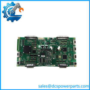
The GE IS200MVREH1A is an MVRE Primary Turbine Protection Terminal Board used in the GE Mark VI turbine control and protection architecture. Its primary job is to interface field protection signals with the associated protection processor. Technical records identify the MVRE board as the signal-acquisition portion of the protection assembly, while the companion PMVP module provides the processing and protection logic. This separation is important when diagnosing a turbine trip circuit because a fault on the terminal board should not automatically be interpreted as a processor failure.
The GE IS200MVREH1A interfaces three magnetic speed-pickup channels along with flame-detection and generator synchronization signals in the documented protection configuration. These signals are used by the associated PMVP protection module for turbine overspeed, flame, and synchronization-related functions. The protection pack is designed for rapid processing and emergency-trip applications, but the processing and voting functions belong to the associated processor rather than the MVRE terminal board itself.
For the GE IS200MVREH1A, exact system compatibility should be established from the complete board marking, associated PMVP module, terminal wiring, and installed Mark VI architecture. The H1A designation identifies a particular MVRE hardware family, while related revisions such as IS200MVREH1ABA and IS200MVREH1ABC exist in technical records. GE’s certification documentation also lists IS200MVREH1A among Mark VIe industrial-control assemblies, so the part should not be treated as an obsolete board with no relationship to later GE control-system documentation.
Technical Specifications
| Parameter | Specification |
|---|---|
| Product Model | IS200MVREH1A |
| Manufacturer | General Electric |
| Functional Acronym | MVRE |
| Product Type | Primary Turbine Protection Terminal Board |
| System Family | GE Mark VI / related Mark VIe protection architecture |
| Associated Processor | PMVP protection module, including IS215PMVPH1A-family hardware |
| Magnetic Speed Inputs | 3 |
| Speed Pickup Function | Turbine speed / overspeed protection signal acquisition |
| Flame Interface | Supported in the documented protection-pack configuration |
| Generator Synchronization | Device 25 synchronization-voltage input supported by the associated protection arrangement |
| Primary Function | Field signal acquisition and interface |
| Protection Processing | Performed by associated PMVP module |
| Voting Logic | Associated PMVP protection module provides the documented protection logic |
| Communication | Board-level connection to associated protection electronics; not a standalone Ethernet controller |
| Terminal Interface | Field wiring terminal interface |
| Related Revisions | IS200MVREH1ABA, IS200MVREH1ABC |
| Environmental Data | Use the applicable Mark VI installation documentation; do not assume values from the newer PMVP pack apply directly to the bare MVRE board |
| Certification | is included in GE/Intertek Mark VIe industrial-control certification documentation |
| Lifecycle | Legacy Mark VI hardware |
The documented PMVP/MVRE protection pack uses a 37-pin D-type connection between the processor module and MVRE board, while the PMVP module itself uses dual IONet Ethernet interfaces and 28 VDC supplied through the terminal-board arrangement. Those specifications describe the complete protection I/O pack, not standalone electrical ratings for the MVRE PCB.
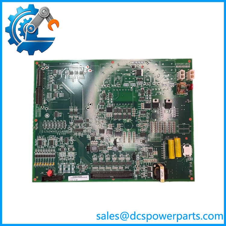
IS200MVREH1A
Main Features and Engineering Considerations
1. Primary Turbine Protection Interface
The is part of the turbine protection signal chain. It receives field-level protection inputs and presents them to the associated PMVP electronics for processing. It should therefore be viewed as a terminal/interface board rather than an independent safety controller.
2. Three Magnetic Speed-Pickup Inputs
The documented protection configuration uses three magnetic speed pickups. These channels provide the speed information required for turbine overspeed protection. Because speed pickup wiring is directly related to trip logic, terminal identification and wiring polarity should be checked against the turbine-specific drawings before replacement.
3. Flame Detection Interface
The MVRE architecture also interfaces flame-detector signals. This allows the associated protection processor to incorporate flame status into the turbine emergency-protection scheme. A field wiring problem can therefore affect more than speed monitoring.
4. Generator Synchronization Input
The protection arrangement includes a generator synchronization voltage input associated with Device 25 functionality. This is not simply another generic analog input. The signal conditioning and expected voltage source must be verified from the installed Mark VI protection drawings.
5. Processor and Terminal Board Are Separate
A common procurement mistake is to describe the MVRE as though it contains the complete protection processor. The PMVP performs the processing and documented voting functions; MVRE provides the field signal interface. Replacing one does not automatically replace the other.
6. Revision Compatibility
Related identifiers such as IS200MVREH1ABA and IS200MVREH1ABC appear in technical records. That does not establish universal interchangeability. A replacement should be compared against the exact board revision, associated PMVP revision, wiring, and application configuration.
7. Safety-Critical Application
This board participates in turbine protection circuitry. Testing should therefore be performed using an approved maintenance procedure and the site’s protection-system test protocol. A board that passes a simple visual inspection or continuity check should not automatically be considered functionally equivalent.
Application Scenarios
- Gas turbine overspeed protection
- Steam turbine protection
- Turbine emergency-trip systems
- Magnetic speed-pickup monitoring
- Flame detection interface
- Generator synchronization monitoring
- GE Mark VI turbine control systems
- GE Speedtronic turbine protection systems
- Legacy Mark VI protection-system maintenance
- Replacement of failed MVRE terminal boards
Engineer’s Guide: Field Pitfalls
Do not confuse MVRE with PMVP.
MVRE is the terminal/signal interface board. The associated PMVP module performs the protection processing and voting functions.
Verify all three speed channels.
A turbine protection configuration using three magnetic pickups depends on correct channel assignment. Do not assume that moving wires one-for-one without checking the cabinet drawing preserves the intended protection architecture.
Check the flame-detector wiring separately.
Flame inputs are part of the protection chain. A board replacement should include verification of the relevant flame input circuits, not only the speed channels.
Do not apply PMVP specifications directly to MVRE.
The -30°C to +65°C temperature range, 28 VDC supply, Ethernet interfaces, processor characteristics, and millisecond response descriptions found in some records refer to the complete PMVP/MVRE protection pack or PMVP module. They should not be published as standalone MVRE specifications without supporting documentation.
Check the exact revision.
, IS200MVREH1ABA, and IS200MVREH1ABC should not be treated as interchangeable solely because they share the MVREH1A base identifier.
Verify the generator synchronization circuit.
The Device 25 input is part of the documented protection arrangement. Confirm the source, scaling, and terminal assignment from the installed system drawings before commissioning.
Inspect the terminal board carefully.
Loose terminal hardware, damaged connectors, contamination, and heat-related PCB damage can create intermittent protection signals that resemble a processor fault.
Test the protection chain after replacement.
For a safety-related turbine protection circuit, functional testing should include the relevant speed, flame, synchronization, and trip paths according to the site’s approved test procedure.
Frequently Asked Questions
What is GE ?
It is a GE MVRE Primary Turbine Protection Terminal Board used in the Mark VI turbine protection architecture.
What does MVRE do?
MVRE provides the field signal interface for turbine protection inputs, including magnetic speed pickups and other protection signals. The associated PMVP module performs the protection processing.
How many magnetic speed inputs are supported?
The documented protection-pack configuration identifies three magnetic speed-pickup inputs.
Does perform the overspeed voting logic?
No. The associated PMVP protection module performs the documented processing and voting functions. MVRE provides the signal-acquisition/interface portion of the assembly.
Does MVRE support flame detection?
Yes. Flame-detector inputs are identified in the documented PMVP/MVRE turbine protection configuration.
Is an Ethernet communication board?
No. It should be classified as a turbine protection terminal/interface board. The dual IONet Ethernet interfaces belong to the associated PMVP module in the documented protection pack.
Is compatible with IS200MVREH1ABA or IS200MVREH1ABC?
They are documented related revisions, but that alone does not establish a drop-in replacement. Verify the complete board revision and the associated PMVP/protection configuration before substitution.
What should be checked before purchasing?
Verify the complete marking, board revision, associated PMVP module, speed-pickup wiring, flame interface, synchronization circuit, terminal arrangement, and turbine-specific protection configuration.
Procurement Note
For a replacement , request photographs of the complete PCB label and connector/terminal side, then compare the revision against the installed board. For used or refurbished inventory, the useful test evidence is not simply “powers on”; the supplier should be able to demonstrate relevant terminal continuity and, where possible, functional verification of the speed, flame, and synchronization signal paths.
The most important procurement distinction is MVRE = field protection interface; PMVP = protection processing. Keeping those functions separate prevents an incorrect substitution based on listings that describe the board simply as a generic “controller” or “turbine protection board.”