Description
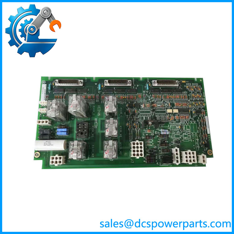
GE IS200ECTBG1ADE | Exciter Contact Terminal Board | EX2100 Redundant Excitation
Key Technical Specifications
| Parameter | Specification |
|---|---|
| Manufacturer | GE General Electric |
| Model | IS200ECTBG1ADE |
| Base Board | IS200ECTBG1A |
| Functional Acronym | ECTB |
| Product Type | Exciter Contact Terminal Board |
| System | Excitation Control |
| Control Configuration | Redundant |
| Auxiliary Contact Inputs | 6 |
| Contact Wetting | 70 VDC nominal |
| Dedicated Trip Contact Outputs | 2 |
| General-Purpose Relay Outputs | 4 Form-C |
| Control Interface | EMIO |
| Backplane Connectors | J405, J408, J415 |
| Terminal Blocks | TB1, TB2 |
| Contact Inputs | Includes 52G and 86G monitoring |
| PCB Configuration | Group 1, normal coating |
| Revision | DE suffix; verify board label before substitution |
The six auxiliary contact inputs are wetted with approximately 70 VDC. The ECTB also provides 70 VDC contact power and monitoring for the 52G and 86G inputs. Four general-purpose Form-C outputs are controlled through the EMIO architecture, while two dedicated trip outputs drive the customer lockout function.
The three 25-pin connectors J405, J408, and J415 provide the interface toward the EMIO M1, M2, and C control sections through the exciter backplane. In the redundant ECTBG1 arrangement, the board receives power associated with both M1 and M2 controller paths.
Product Introduction
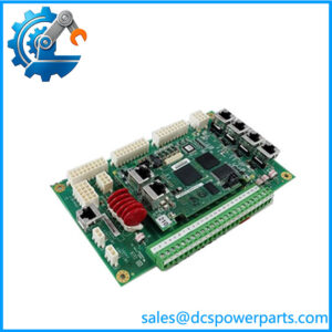
The is an Exciter Contact Terminal Board (ECTB) used in GE’s excitation-control architecture. It provides the field-side contact interface for excitation equipment, combining auxiliary contact monitoring, generator-status inputs, customer trip signaling, and general-purpose relay outputs on one dedicated terminal board. It is therefore not a generic Mark VI digital I/O board; its circuitry and signal paths are specifically associated with the excitation system.
The is the Group 1 ECTB configuration intended for redundant control. GE’s ECTB architecture distinguishes this from the ECTBG2 configuration used for simplex control. That distinction is significant during replacement because the board is integrated with the M1/M2 controller arrangement, EMIO boards, and EBKP backplane rather than operating as an independent field-I/O module.
IS200EXHSG3REC
Application Scenarios & Field Pitfalls — The Engineer’s Perspective
Engineering Pain Point
A contact fault in an excitation system can be difficult to isolate because the same symptom may originate from field wiring, contact-wetting voltage, the ECTB, EMIO circuitry, or the redundant controller path. The sits between these elements, so a board replacement should be approached as an excitation-system intervention rather than a routine PLC I/O replacement.
Typical Applications
- GE excitation systems — interface for excitation-related contact inputs and outputs.
- Steam turbine generator excitation — generator status, trip, lockout, and auxiliary contact monitoring.
- Gas turbine generator packages — contact interface within excitation cabinets.
- Redundant excitation control systems — specifically the ECTBG1 architecture.
- Mark VI legacy maintenance — replacement of failed ECTB hardware during planned turbine outages.
Technical Pitfalls to Avoid
- Do not confuse G1 with G2.
ECTBG1 is designated for redundant control, while ECTBG2 is used for simplex configurations. A visually similar G2 board should not be treated as a direct substitute without confirming the system architecture. - Do not treat the six inputs as ordinary 24 VDC digital inputs.
The documented ECTB design uses approximately 70 VDC contact wetting. Applying assumptions from conventional PLC input modules can result in an incorrect wiring or diagnostic procedure. - Pay particular attention to 52G and 86G.
The ECTB provides power and monitoring for these dedicated contact inputs. They have system-level significance, so a wiring or contact-wetting fault can be interpreted as an excitation or generator-status problem rather than a simple I/O fault. - Check the EMIO and EBKP interfaces.
The four Form-C relay outputs are controlled through EMIO, and the ECTB connects through J405, J408, and J415. A suspected ECTB failure should therefore be evaluated together with connector condition, backplane connections, EMIO diagnostics, and field wiring. - Keep the complete suffix in the procurement record.
is more specific than simply IS200ECTBG1A. The available part-number reference identifies the board as Group 1 with a three-character revision designation and normal PCB coating. For a shutdown-critical replacement, compare the complete board marking rather than purchasing solely against the shortened base model. - Do not rely on generic relay ratings without checking the system drawing.
Secondary technical references commonly associate the general-purpose Form-C relays with 125 VDC circuits, but the actual field application and external circuit protection must be confirmed from the installed documentation before using those figures for design or modification work.
Related Products
- GE IS200ECTBG1A — base ECTBG1 Exciter Contact Terminal Board designation; the underlying functional board family for .
- GE IS200ECTBG2A — ECTB Group 2 configuration for simplex control; functionally related but intended for a different control architecture.
- GE IS200EMIO — Exciter Main I/O board that controls the ECTB’s general-purpose relay outputs and handles associated feedback.
- GE IS200EBKP — Exciter Backplane used to interconnect the excitation-control boards.
- GE IS200EXHSG3REC — Exciter High-Speed Relay Driver Board used for high-speed excitation relay functions; it is complementary to the ECTB rather than a substitute.
- GE IS200EDEXG1A — Exciter De-Excitation Board associated with de-excitation functions.
- GE Excitation Control — excitation-control platform containing the ECTB, EMIO, EXHS, and related boards.
- GE Mark VI — turbine-control platform associated with GE’s broader excitation and turbine-control architecture.
- GE IS200EXHS series — high-speed exciter relay-driver family used where the configuration requires high-speed excitation switching.
Procurement note: Specify exactly on the RFQ or spare-parts record. For a planned outage, confirm the installed system is using ECTBG1 redundant control, then compare the board suffix, PCB revision, EMIO arrangement, EBKP connections, and field-terminal wiring. A matching ECTB family number alone is not sufficient evidence of interchangeability.