Description
GE IS200ECTBG1ABB Excitation Contact Terminal Board
Product Introduction
The General Electric IS200ECTBG1ABB is an Excitation Contact Terminal Board used in GE Mark VI turbine control and EX2100 excitation-control architectures. Its job is to provide a dedicated interface for excitation-related contact inputs and relay outputs rather than perform the processing functions of a controller or general-purpose I/O processor. The board belongs to the ECTBG1 group, which is identified for redundant control configurations. In a typical installation, the GE IS200ECTBG1ABB works with EMIO control hardware and associated excitation I/O boards to transfer generator and excitation contact status between field wiring and the control system.
The GE IS200ECTBG1ABB provides six auxiliary contact inputs with approximately 70 VDC contact wetting. The documented contact functions include 52G generator-status monitoring and 86G lockout monitoring. The board also provides two trip contact outputs and four general-purpose Form-C relay outputs. The general-purpose relay contacts can be used for excitation-system functions such as 94EX and 30EX, with the EMIO board controlling the associated relay outputs.
From a maintenance perspective, the GE IS200ECTBG1ABB should be treated as application-specific excitation hardware. A replacement should not be selected solely because another ECTB board has the same basic function. ECTBG1 and ECTBG2 have different control-mode applications, and the complete suffix should be matched against the installed Mark VI/EX2100 cabinet documentation. The board also relies on the M1/M2 power architecture in redundant installations, so connector wiring, contact-wetting voltage, associated EMIO hardware, and the exact terminal-board revision should be checked before commissioning.
Technical Specifications
| Parameter | Specification |
|---|---|
| Product Model | IS200ECTBG1ABB |
| Manufacturer | General Electric |
| Product Type | Excitation Contact Terminal Board |
| Functional Acronym | ECTB |
| System | Mark VI / EX2100 Excitation Control |
| Control Architecture | Redundant |
| Auxiliary Contact Inputs | 6 |
| Contact Wetting Voltage | 70 VDC nominal |
| Contact Wetting Range | Approximately 63–84 VDC reported for the ECTB family |
| Trip Contact Outputs | 2 |
| General-Purpose Relay Outputs | 4 |
| General-Purpose Relay Type | Form-C |
| Typical Contact Functions | 52G generator status, 86G lockout, excitation trip/general-purpose functions |
| Control Interface | EMIO-associated architecture |
| Power Architecture | M1/M2 supplies in redundant configuration |
| Backplane/Control Connections | J405, J408, J415 25-pin connections reported for ECTB family |
| Primary Documentation | GEI-100457; GEH-6632 |
| Mounting / Mechanical Data | Verify against cabinet drawing and installed board revision |
| Operating Temperature | Do not treat reseller-published temperature figures as a substitute for the cabinet/system specification |
The 70 VDC contact-wetting information and connector arrangement are reported for the ECTB family; the exact cabinet wiring should be confirmed against the applicable GE drawings before field replacement.
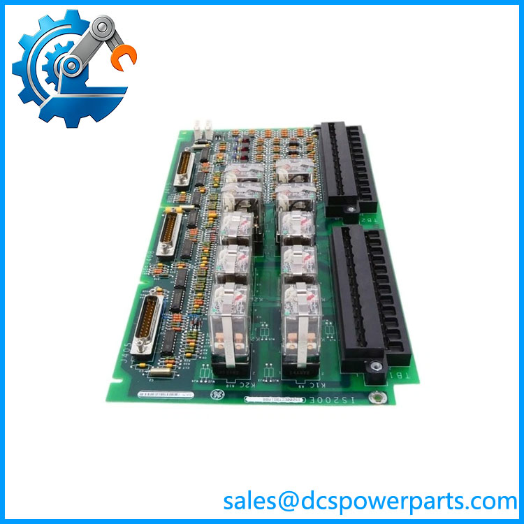
IS200ECTBG1ABB
Main Features and Engineering Considerations
1. Dedicated excitation contact interface
The is designed around excitation-system contact handling. It should not be represented as a conventional analog or digital PLC I/O module. Its six auxiliary contact inputs are powered by the board for contact wetting, with 52G and 86G serving documented generator-status and lockout functions. This voltage is substantially different from the 24 VDC contact inputs commonly encountered on modern PLC systems. Applying an assumed 24 VDC field-wiring scheme without checking the original cabinet documentation is a significant replacement risk.
2. Redundant ECTBG1 configuration
The G1 configuration is associated with redundant control. ECTBG1 and ECTBG2 should therefore not be treated as interchangeable merely because both are ECTB boards. ECTBG1 installations use the M1/M2 control architecture, while ECTBG2 is associated with simplex applications. This distinction matters when replacing an obsolete board in an operating excitation cabinet.
3. Relay output architecture
The board contains two trip contact outputs and four general-purpose Form-C relay outputs. The general-purpose outputs are controlled through associated EMIO hardware. When troubleshooting an output problem, technicians should therefore check the ECTB, EMIO command path, relay wiring, and external circuit together rather than assuming that a failed field output automatically means the terminal board is defective.
4. Revision control matters
The full identifier should be used for procurement. The base identifier IS200ECTBG1A does not contain enough information by itself to establish complete interchangeability. Board artwork, functional revision, connector configuration, and cabinet-specific implementation should be checked against the failed unit. For legacy Mark VI equipment, a physical board inspection and comparison of connector labels can prevent an otherwise avoidable commissioning problem.
5. Procurement and testing
For a replacement, verify the complete part number, board revision, condition of terminal blocks, connector condition, relay operation, contact-wetting circuit, and compatibility with the installed EMIO and M1/M2 architecture. If the board is supplied as repaired or surplus equipment, functional testing should include contact-input verification and relay-output testing under controlled conditions before it is returned to a turbine excitation cabinet.
Application Scenarios
- GE Mark VI turbine control systems
- GE EX2100 excitation-control systems
- Generator excitation contact monitoring
- Generator 52G status monitoring
- Generator 86G lockout monitoring
- Excitation trip circuits
- General-purpose excitation relay interfaces
- Redundant excitation-control cabinets
Engineer’s Guide: Field Pitfalls
Do not substitute by the base model alone.
ECTBG1 and ECTBG2 serve different control architectures. The installed system should determine the replacement.
Do not assume 24 VDC contact inputs.
The ECTB uses approximately 70 VDC contact wetting for its documented auxiliary contact inputs. Confirm the field circuit before applying external test voltage.
Do not confuse ECTB with an EMIO board.
The ECTB provides the contact-terminal interface; the EMIO participates in controlling the general-purpose relay outputs.
Check the 52G and 86G circuits carefully.
These are not interchangeable generic status contacts. The 86G circuit is associated with generator lockout functionality, making incorrect wiring particularly undesirable during commissioning.
Verify M1/M2 architecture.
The redundant configuration receives its required power through the applicable excitation-control power architecture. Connector and backplane wiring should be checked before energization.
Inspect the complete suffix.
should be matched against the failed board rather than ordering an IS200ECTBG1A based only on the family designation.
Frequently Asked Questions
What is the ?
It is a GE Excitation Contact Terminal Board used in Mark VI/EX2100 excitation-control applications. It provides excitation-related contact inputs and relay outputs rather than functioning as a standalone PLC processor.
Is an analog input module?
No. Its documented role is contact I/O for the excitation system, including auxiliary contact monitoring and relay contact outputs.
Is used in simplex or redundant control?
The configuration is identified for redundant control. ECTBG2 is associated with simplex applications.
How many auxiliary contact inputs are provided?
The documented ECTB configuration provides six auxiliary contact inputs, with 70 VDC contact wetting. The 52G and 86G circuits are among the documented contact functions.
How many relay outputs are provided?
The board has two trip contact outputs and four general-purpose Form-C relay outputs. The general-purpose outputs are controlled through associated EMIO hardware.
What manual should be checked?
GEI-100457 is identified as the part-specific ECTB manual. GEH-6632 is also referenced for ECTB configuration and related Mark VI excitation hardware.
What should be verified before purchasing a replacement?
Confirm the complete identifier, board revision, redundant-control architecture, EMIO compatibility, M1/M2 power arrangement, connector configuration, terminal condition, and the actual 52G/86G and relay wiring in the cabinet.
Procurement Note
For a legacy GE Mark VI/EX2100 installation, should be purchased and inspected as an exact excitation terminal-board assembly, not as a generic GE digital I/O card. The most important checks are the complete suffix, redundant architecture, board revision, EMIO relationship, M1/M2 power arrangement, and the 70 VDC contact-wetting circuit. A board that appears electrically similar but belongs to a different ECTB configuration can create a wiring or control-architecture mismatch.