Description
Key Technical Specifications
| Parameter | IC697CHS770 |
|---|---|
| Manufacturer | GE Fanuc |
| Series | Series 90-70 |
| Product Type | Redundant PLC Rack |
| Rack Configuration | Dual redundant |
| Mounting | Rear / panel mount |
| Rack Sections | 2 |
| Module Positions | 6 per section |
| Power Supply Position | 1 per section |
| Total Backplane Positions | 12 module positions + 2 power-supply positions |
| Standard Module Width | 1.6 in |
| VME Module Support | Applicable IC687 VME I/O and communication modules |
| I/O Bus Current | 0.5 A |
| Dimensions | 11.15 × 19.00 × 7.5 in |
| Rack Identification | Four jumpers behind power supply |
| System Application | Hot Standby / redundant PLC |
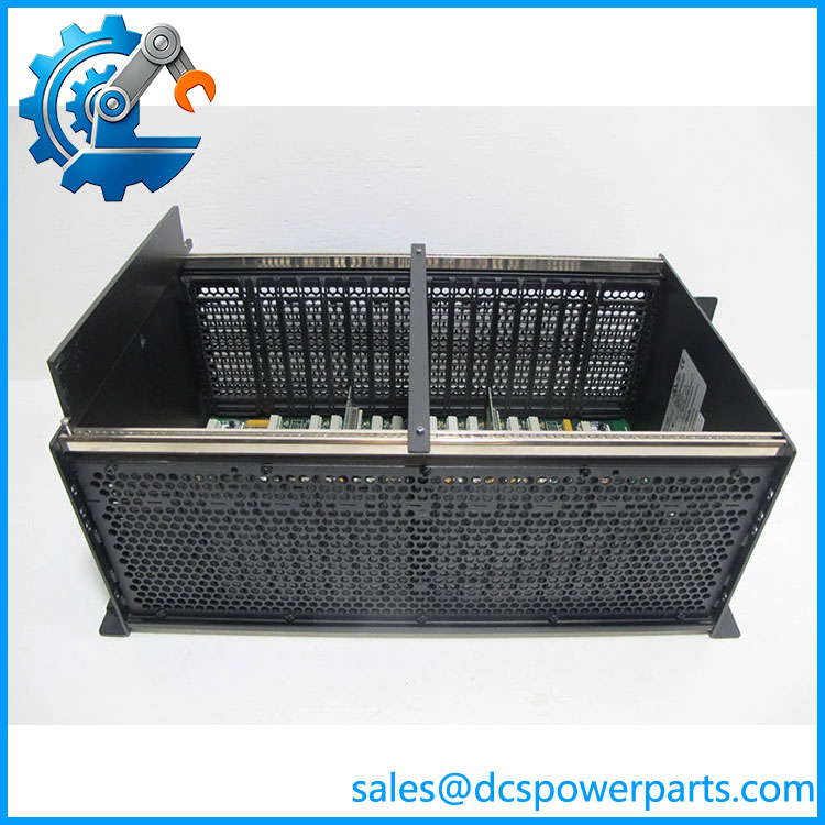
The original Series 90-70 documentation describes the IC697CHS770 as a redundant rear-mount rack with two separate sections, each containing six backplane slots and one power-supply position. The rack can accept standard Series 90-70 modules as well as applicable half-slot VME modules.
The published overall dimensions are approximately 11.15 × 19.00 × 7.5 inches (283 × 483 × 190 mm). The rack uses 1.6-inch spacing for standard Series 90-70 modules, while applicable VME modules use 0.8-inch spacing and one slot.
IC697CHS770
Product Introduction
GE Fanuc IC697CHS770 Redundant PLC Rack
The GE Fanuc IC697CHS770 is the rear-mount redundant rack for the Series 90-70 PLC platform. Its backplane is divided into two independent sections, allowing redundant controller configurations to share one physical rack assembly.
This rack is particularly important in Hot Standby CPU redundancy applications. The Series 90-70 redundancy documentation specifically lists IC697CHS770 and the front-mount IC697CHS771 as the redundant rack options, while also describing the communications hardware required to synchronize the two CPUs and transfer I/O data.
Application Scenarios & Field Pitfalls — Engineer’s Perspective
Engineering Pain Point
The IC697CHS770 is not simply a larger version of the standard 90-70 rack. Its internal backplane is divided into two sections, and the rack architecture is intended for redundant controller applications.
Typical Applications
- Series 90-70 Hot Standby CPU redundancy — the rack is specifically listed as a supported redundant rack.
- Dual PLC configurations — two independent controller sections can occupy the same physical rack assembly.
- Redundant process-control systems — useful where controller availability is more important than a conventional simplex rack arrangement.
- Mixed IC697 / VME configurations — the redundant rack supports standard IC697 modules and applicable IC687 VME I/O and communication hardware.
Technical Pitfalls to Avoid
- Do not substitute IC697CHS790 blindly.
IC697CHS790 is a standard nine-slot rack, while is a redundant dual-section rack. They serve different system architectures even though both belong to Series 90-70. - Verify the mounting orientation.
is the rear/panel-mount redundant rack. IC697CHS771 provides the corresponding front/rack-mount redundant configuration. - Check the power-supply arrangement.
Each redundant rack section has its own power-supply position. The installed power supply and redundancy design must be checked before replacing the chassis. - Check VME slot requirements carefully.
Applicable VME modules use 0.8-inch spacing and consume one slot, whereas standard Series 90-70 modules use 1.6-inch spacing. A physical slot count alone can therefore be misleading.
Related Products
- IC697CHS771 — redundant Series 90-70 rack with front/rack mounting rather than the rear/panel mounting of .
- IC697CHS750 — standard five-slot rear-mount Series 90-70 rack; not a redundant chassis.
- IC697CHS790 — standard nine-slot rear-mount Series 90-70 rack; intended for simplex configurations.
- IC697CHS791 — standard nine-slot front-mount Series 90-70 rack.
- IC697CHS782 — 17-slot VME Integrator rack for Series 90-70 applications and third-party VME hardware.
- IC697CGR772 — Series 90-70 Hot Standby CPU with 2K discrete I/O, 512 KB memory, and 96 MHz processor.
- IC697CGR935 — Hot Standby CPU with 12K discrete I/O and 1 MB memory.
- IC697PWR710 — 120/240 VAC or 125 VDC Series 90-70 power supply, 50 W.
- IC697PWR724 — 24 VDC, 90 W Series 90-70 power supply.
- IC697CBL803 — 3 ft / 0.9 m cable used for the redundancy communications connection between applicable RCM and BTM modules.
Procurement Note
For procurement, identify the item as:
GE Fanuc — Series 90-70 Redundant Rack — Rear/Panel Mount
The critical checks are redundant vs. standard architecture, rear vs. front mounting, power-supply configuration, and the installed IC697/IC687 module mix. The chassis itself does not determine whether the complete redundant system will operate; the CPU, Redundancy Communications Module, Bus Transmitter/Receiver hardware, power supplies, and associated cabling must all match the intended redundancy architecture.
Obsolete-system procurement should be based on the rack nameplate and existing cabinet drawing rather than dimensions alone.