Description
Key Technical Specifications
| Parameter | IC687BEM713 |
|---|---|
| Manufacturer | GE Fanuc |
| Model | IC687BEM713 |
| Product Type | Bus Transmitter Module |
| PLC Family | Series 90-70 |
| Module Format | Half-slot VME |
| Primary Function | Bus expansion / redundancy communication |
| Effective Data Rate | 500 Kbytes/s |
| Maximum Expansion Racks | 7 |
| Maximum Cable Length | 50 ft |
| Backplane Supply | 5 VDC |
| Current Consumption | Approx. 1.4 A |
| Communication Interface | High-speed parallel bus |
| Programmer Interface | Supported |
| Mounting | Series 90-70 / compatible VME rack |
| Typical Application | I/O expansion and Hot Standby CPU redundancy |
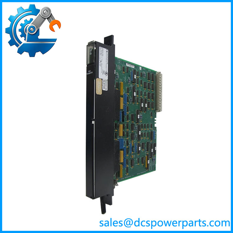
GE Fanuc documentation identifies IC687BEM713 as the ½-slot version of the Bus Transmitter Module (BTM). In an I/O expansion system, the BTM carries the I/O bus signals through a cable to a Bus Receiver Module in the first expansion rack; in a Hot Standby CPU redundancy system, it works with the Redundancy Communications Module.
The published 500 Kbytes/s effective data rate, 50-foot maximum cable length, and support for up to seven expansion racks are also consistently associated with this model.
Product Introduction
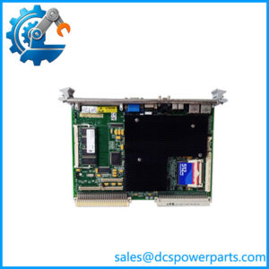
GE Fanuc IC687BEM713 Bus Transmitter Module
The GE Fanuc IC687BEM713 is a half-slot Bus Transmitter Module for the Series 90-70 architecture. Its job is to extend the PLC I/O bus from the main rack toward expansion racks and, in redundant systems, provide the required communication path between the Bus Transmitter Module and Redundancy Communications Module.
This module is easy to misidentify because the same hardware appears in more than one Series 90-70 architecture. In a conventional expansion system, it is part of the rack-to-rack I/O bus; in an Enhanced Hot Standby configuration, it becomes part of the CPU redundancy communication path. The actual cabinet architecture should therefore be checked before replacement.
IC687BEM713
Application Scenarios & Field Pitfalls — Engineer’s Perspective
Engineering Pain Point
A failed BTM can look like a rack, CPU, or I/O problem because communication with downstream hardware may disappear at the same time. The IC687BEM713 sits directly in that communication path, so a poor connection or incorrect module selection can affect an entire expansion structure.
Typical Applications
- Series 90-70 I/O expansion — transmits the I/O bus between the main rack and expansion rack.
- Hot Standby CPU redundancy — installed with the RCM in the redundant controller architecture.
- Large legacy PLC cabinets — supports systems using multiple expansion racks.
- PACSystems RX7i installations — GE documentation lists among supported Series 90-70 bus expansion modules.
Technical Pitfalls to Avoid
- Do not confuse the BTM with the Bus Receiver Module.
The is the transmitting-side module. The expansion rack requires the appropriate receiving hardware for the particular Series 90-70 configuration. - Check whether the system is redundant.
In a Hot Standby CPU system, GE documentation requires a BTM and RCM arrangement in both the primary and secondary PLCs. The IC697CHS770/CHS771 redundant rack architecture also uses the half-slot and a specific interconnection cable. - Verify cable length and physical routing.
The documented maximum cable length is 50 ft. Long cable runs, poor shielding, damaged connectors, or incorrect routing can produce intermittent expansion-rack communication faults. - Check module width before ordering.
is the half-slot version. Do not substitute a full-width Series 90-70 communication module simply because the electrical function appears similar. - Do not trust generic descriptions such as “analog input module.”
Some current listings misclassify this part. The Series 90-70 documentation clearly identifies as a Bus Transmitter Module.
Related Products
- IC697BEM713 — full-size Series 90-70 Bus Transmitter Module. The is the half-slot version.
- IC697BEM711 — Series 90-70 bus expansion hardware used in compatible rack configurations.
- IC697BEM733 — Series 90-70 remote I/O scanner; different communication architecture from the BTM.
- IC697BEM731 — Genius Bus Controller; intended for Genius I/O rather than the BTM expansion function.
- IC697CHS770 — rear-mount redundant rack supporting the half-slot BTM/RCM arrangement.
- IC697CHS771 — front-mount redundant Series 90-70 rack.
- IC697CBL803 — 3-foot cable used to connect the half-slot RCM and BTM in the redundant rack configuration.
- IC687BEM742 — FIP Bus Controller from the same IC687 VME family, but with a completely different communication function.
- Series 90-70 Bus Receiver Module — required at the expansion-rack side when the BTM is being used for rack-to-rack I/O expansion.
Procurement Note
For purchasing records, identify the part as:
GE Fanuc — Series 90-70 Half-Slot Bus Transmitter Module — 500 Kbytes/s — Up to 7 Expansion Racks
Before approving a replacement, check:
- Main rack and expansion-rack architecture
- Simplex vs. Hot Standby configuration
- BTM/RCM arrangement
- Correct mating expansion hardware
- Cable type and length
- Module width and revision
One particularly important distinction: is not simply a generic “bus expansion card.” In the original Series 90-70 documentation, its role changes depending on whether it is being used for ordinary I/O rack expansion or as part of a Hot Standby redundancy system.