Description
Key Technical Specifications
| Parameter | Value |
|---|---|
| Manufacturer | GE Multilin / GE Vernova |
| Product family | Multilin F650 |
| Product type | Feeder protection relay / digital bay controller |
| Protection functions | Overcurrent, over/undervoltage, frequency, breaker failure, and autoreclose, subject to configuration |
| Auxiliary supply | HI-range variants support 110–250 V DC or 120–230 V AC, subject to the exact model |
| Communication | Ethernet and serial options depend on the installed communication boards |
| Digital I/O | Depends on the fitted I/O boards |
| Display | Depends on the ordered display configuration |
| Communication protocols | Depends on configuration; options may include IEC 61850, Modbus, DNP 3.0, and IEC 60870-5-104 |
| Operating temperature | Published F650 specifications generally list −10°C to +60°C; verify the exact hardware revision |
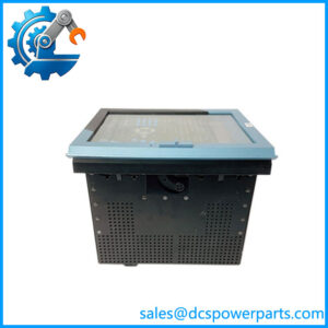
| Installation | Panel-mounted protection relay |
| Exact configuration suffixes | Require nameplate or OEM ordering-code confirmation |
The HI supply range and available protection functions are documented in the F650 technical literature. They should not be used to infer the exact I/O or communications configuration from the supplied model string.
Application Scenarios & Pain Points
A feeder fault can escalate quickly when protection settings, breaker logic, or current-transformer wiring are incorrect. During a relay replacement, matching the hardware alone is not enough; the protection scheme must also be preserved and validated.
Typical applications
- Distribution substations: Phase and ground overcurrent protection for outgoing feeders.
- Industrial switchgear: Breaker control, trip-circuit supervision, and breaker-failure logic where configured.
- Bus transfer schemes: Voltage monitoring, synchronism checks, and control logic for approved transfer arrangements.
- Power system monitoring: Event recording, waveform capture, and metering to help diagnose faults and disturbances.
Field note: Before removing the original relay, save its settings file and record CT/VT ratios, trip logic, communication addresses, and assigned output contacts. A replacement with different I/O hardware can require wiring and configuration changes even when the protection functions appear similar.
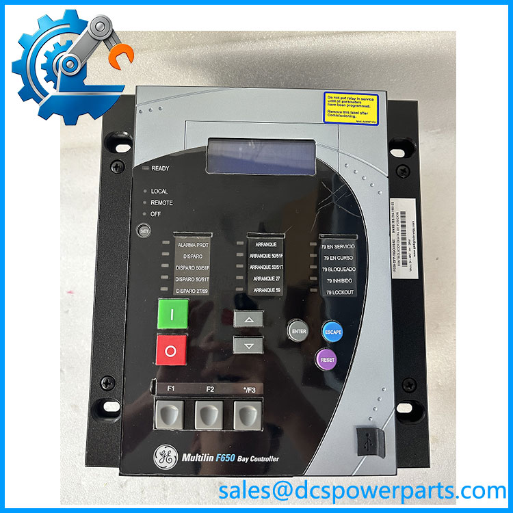
F650-BFP-FIGO-HI-6E
Related Products
These products are related to the F650 protection system but are not automatic substitutes.
- GE Multilin F650 — The same feeder protection and bay controller family. Select the exact configuration based on the installed ordering code.
- GE Multilin F650 with HI supply — A high-range auxiliary supply variant for compatible AC/DC station supplies. Confirm the actual supply designation.
- GE Multilin with redundant HI supply — A redundant-supply configuration where supported. Not interchangeable with every standard-supply variant.
- GE Multilin CIO remote I/O module — Expands available I/O through the supported remote CAN bus arrangement; requires a compatible configuration.
- GE Multilin ML2400-F-HI-HI-A2-A2-A6-G1 — Industrial Ethernet switch listed in accessory literature; supports network infrastructure rather than relay protection.
- GE Multilin C650 — A related protection and control platform with a different hardware and ordering structure. Requires application-level engineering review.
- GE Multilin D400 — Substation automation and gateway equipment for a different system role; not a direct relay replacement.
The accessory documentation identifies the CIO remote I/O family and ML2400 switch as related equipment. Verify the exact model and application before ordering.
The Engineer’s Guide: Field Pitfalls to Avoid
Warning 1 — Incorrect ordering-code interpretation
- Compare the complete model string against the physical nameplate.
- Confirm the display, communications boards, I/O slots, supply range, and protocol options.
- Resolve the discrepancy in
-BFP-FIGO-HI-6Ebefore placing a configuration-sensitive order.
Warning 2 — CT/VT wiring or protection-setting mismatch
- Record CT and VT ratios and polarity.
- Check phase rotation and ground-current measurement arrangements.
- Validate pickup levels, time delays, directional settings, and breaker-failure logic against the approved protection study.
- Perform commissioning tests before returning the feeder to service.
Warning 3 — Communication and firmware differences
- Confirm the supported firmware and configuration software for the exact hardware revision.
- Check protocol support, IP settings, serial parameters, and time synchronization.
- Verify event reporting and communication with the station control system after installation.
Frequently Asked Questions (FAQ)
1. What is the GE -BFP-FIGO-HI-6E used for?
It appears to refer to a configuration of the GE Multilin feeder protection relay family. The provides feeder protection, breaker control, monitoring, and bay automation. The exact hardware options in the supplied designation need verification.
2. What does the HI suffix mean on a GE relay?
The ordering documentation uses HI for the high-range auxiliary supply option, rated for 110–250 V DC or 120–230 V AC in the published configuration. Verify the nameplate and applicable manual before connecting station power.
3. Can I replace this relay with another model?
Not solely because both units belong to the family. Differences in I/O boards, communications, supply options, display, and protocol configuration can affect installation and operation. Compare the complete ordering code and confirm compatibility with the protection scheme.
4. How can I confirm the relay’s exact configuration?
Check the nameplate and the OEM ordering record. Record the display option, serial and Ethernet communication boards, I/O board selections, auxiliary supply, language, and protocol. If the code remains ambiguous, obtain written confirmation before purchasing.
5. What testing should be requested for a used relay?
Ask for evidence of power-up diagnostics, display operation, communication checks, input measurement tests, output-contact operation, and event-recording functionality where applicable. For protection-critical use, perform a site-approved secondary injection and trip-circuit commissioning test.
6. Does the support IEC 61850?
The family supports IEC 61850 on applicable configurations, including Edition 2 in documented versions. Protocol availability depends on the installed communications hardware and firmware, so verify the exact unit before assuming support.
7. What is the delivery lead time for -BFP-FIGO-HI-6E?
Lead time depends on the availability of the exact configuration and whether the unit needs testing or sourcing. Ask the supplier to confirm the complete model string, actual stock condition, test evidence, warranty, and dispatch date. For a planned outage, do not accept a generic availability statement as confirmation that this particular configuration is ready to ship.