Description
Key Technical Specifications
| Parameter | Specification |
|---|---|
| Manufacturer | GE |
| Model | EVMECNTM13 |
| Product Family | EX2100 Excitation Control |
| Board Family | EXTB |
| Product Type | Exciter Terminal Board |
| Control Configuration | Simplex |
| Primary System | GE EX2100 |
| Functional Role | Excitation-system field/terminal interface |
| Application | Generator excitation and field control |
| Associated Hardware | EX2100 control boards and EDEX hardware |
| Architecture | Excitation terminal/interface circuitry |
| Lifecycle | Legacy / obsolete-family hardware |
| Replacement Basis | Exact board revision and EX2100 configuration |
The available references specifically associate the EXTB board family with EX2100 excitation systems and describe EVMECNTM13 as an EXTB board used in a simplex configuration.
I would not publish unverified voltage, current, channel-count, connector, or dimensional specifications for this part. The available online data is contradictory, and some listings appear to have copied specifications from unrelated GE products. For an excitation-system spare, that is not a harmless catalog error.
Product Introduction
GE EVMECNTM13
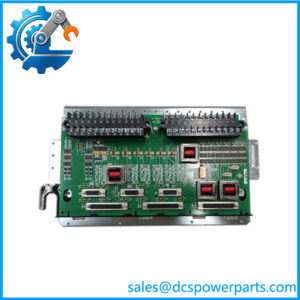
The GE EVMECNTM13 is an EXTB-series exciter terminal board associated with the GE EX2100 excitation-control platform. It provides the interface between the excitation-system control hardware and field-side/control-system connections, rather than functioning as a conventional standalone PLC CPU or generic I/O module.
Its importance is practical. An incorrect terminal-board configuration can prevent an otherwise healthy system from operating correctly. For replacement work, the exact architecture, simplex/dual configuration, mating boards, wiring, and revision level need to be matched.
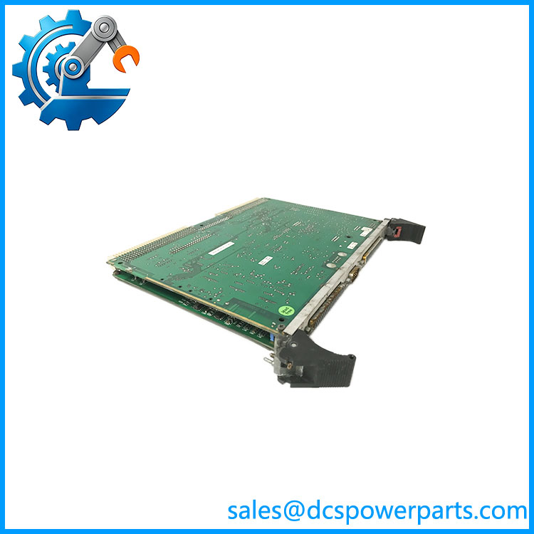
EVMECNTM13
Application Scenarios & Field Pitfalls
Engineering Pain Point
Generator excitation faults are rarely forgiving. A terminal-board problem can present as an excitation-control fault, missing field feedback, incorrect contactor status, or an inability to establish the required excitation sequence. Before replacing the EVMECNTM13, trace the affected signal from the control hardware through the terminal/interface circuitry to the field device.
Typical Applications
- Power Generation — Generator excitation and voltage-regulation systems using GE equipment.
- Steam Turbine Generators — Excitation-system interface for synchronous generators.
- Gas Turbine Generators — Generator field-control and excitation-system terminal interfacing.
- Industrial Power Generation — -based excitation systems for large synchronous machines.
Technical Pitfalls to Avoid
- Do not treat EVMECNTM13 as a generic PLC I/O module.
The available evidence identifies it as an EXTB exciter terminal board for systems. Generic descriptions claiming large numbers of analog/digital channels should not be used for engineering decisions. - Verify simplex versus redundant architecture.
The available EXTB description identifies this configuration as a simplex control model. Do not substitute a board from a redundant/dual architecture without checking the system drawings. - Check the mating boards.
Terminal boards are part of an engineered excitation assembly. Connector compatibility alone does not prove functional compatibility. - Document every field connection before removal.
Excitation-system wiring can include signals directly associated with generator field control. Photographing terminal positions and recording wire numbers is cheap insurance. - Do not trust copied Internet specifications.
Some sources describe as a VME timing board, while others describe it as a motion-control or generic embedded I/O module. Those descriptions are mutually incompatible. - Inspect terminal connections before condemning the PCB.
Loose conductors, oxidized terminals, damaged connectors, and field wiring faults can generate symptoms that look like board failure. - Check excitation-system diagnostics separately from field wiring.
A control-side diagnostic and a field-side wiring fault can produce similar symptoms at the operator interface. Work from the signal path rather than replacing boards by trial and error. - Verify the exact nameplate.
should be matched by the complete board identification, revision, artwork/assembly number, and installed configuration. - Be careful with EDEX references.
Available descriptions associate EXTB hardware with EDEX hardware in excitation/de-excitation functions. Confirm the actual system drawing before assuming a particular EDEX combination. - Treat this as legacy excitation hardware.
Long-term support and replacement options can be considerably more constrained than for current control-system hardware. Maintaining a verified spare is often more practical than waiting for an emergency replacement.
Related Products
- GE EDEX Board — Associated with excitation/de-excitation functions. The available documentation specifically references EDEX hardware in conjunction with the EXTB assembly.
- GE Excitation Control — The primary system family for . The controller performs the actual excitation regulation and control functions, while the EXTB provides field/interface termination.
- GE EXTB Series — The terminal-board family to which belongs. Other EXTB variants may have different system configurations, so the exact suffix should be checked before substitution.
- GE Control Board Assembly — The associated control electronics that process excitation-control functions. Compatibility with depends on the specific architecture.
- GE Excitation Power Bridge Hardware — Provides the controlled power path to the generator field. It performs a fundamentally different function from the terminal board.
- GE Generator Field Interface Hardware — Complementary field-side equipment used with excitation systems. Exact selection depends on generator field voltage/current and excitation topology.
- GE Mark VI Turbine Control Hardware — Often found in the same power-generation installation, but it performs turbine control rather than generator excitation. It should not be confused with hardware.
- GE Mark VIe Control Hardware — Newer GE control-system family frequently encountered in modern turbine-generator installations. It is not a direct functional replacement for EXTB hardware.