Description
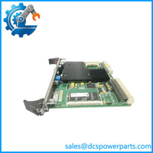
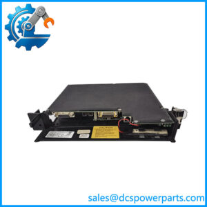
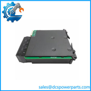
GE DS200TCPDG1B
Key Technical Specifications
| Parameter | Specification |
|---|---|
| Product Model | DS200TCPDG1B |
| Manufacturer | General Electric |
| Product Family | Mark V SPEEDTRONIC |
| Functional Acronym | TCPD |
| Product Type | Power Distribution Module |
| Functional Revision | B |
| Distribution Voltage | 125 VDC |
| Fuse Quantity | 36 |
| Fuse Status LEDs | 36 |
| Fault LEDs | 2 red LEDs |
| Toggle Switches | 8 |
| Signal-Wire Terminals | 4 |
| Main Connector | 1 × 10-pin |
| Fuse Identification | FU1, FU2, FU3, etc. |
| Switch Identification | SW-designated switches |
| Ground Reference Jumper | BJS |
| Power Conversion Association | DACA PCB |
| System Application | GE Mark V turbine control |
| Installation | Mark V control cabinet / power-distribution section |
| Software Configuration | None on the TCPD board itself |
The documented DS200TCPDG1B uses 36 separately fused circuits, with an associated OK LED for each fuse. The board also has eight toggle switches, four signal-wire terminals, one 10-pin connector, and two red fault indicators. The available technical documentation identifies the distributed supply as 125 VDC.
Product Introduction
The GE DS200TCPDG1B is a Mark V TCPD power distribution module used to distribute and monitor DC power inside a GE SPEEDTRONIC turbine control system. It is a power-interface board rather than a turbine control processor. The board’s 36 fused circuits, local status LEDs, and eight toggle switches allow individual power paths to be monitored and controlled during system operation and maintenance.
The board is a B functional revision of the DS200TCPDG1 parent design. The TCPD works within the larger Mark V power architecture, with the DACA board handling the associated power conversion function. For maintenance work, the fuse-by-fuse indication is particularly useful because an extinguished OK indicator can identify a failed fuse circuit without relying solely on cabinet-level diagnostics.
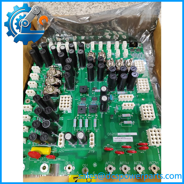
DS200TCPDG1B
Application Scenarios & Field Pitfalls — The Engineer’s Perspective
Engineering Pain Point
A TCPD fault can look like a downstream control-board failure when the actual problem is a missing distribution voltage or blown individual fuse. The DS200TCPDG1B provides local fuse-status indication specifically to help isolate these conditions. At the same time, replacing a fuse without identifying why it opened can simply return the system to another failure. The 125 VDC distribution circuit should therefore be treated as part of the Mark V power architecture, not as a collection of independent low-voltage control circuits.
Typical Applications
- GE Mark V gas turbine control — distribution of DC power to control-system circuits within the cabinet.
- Mark V power-distribution sections — individual fused branches can be monitored through the board’s 36 OK indicators.
- Turbine maintenance and troubleshooting — local fuse and fault indication assists circuit-level diagnosis.
- Legacy SPEEDTRONIC systems — replacement of aging TCPD hardware while retaining the existing Mark V architecture.
Technical Pitfalls to Avoid
- Do not confuse TCPD with TCPS.
The DS200TCPDG1B is a power distribution board. The Mark V family also contains dedicated DC power-supply input boards such as the DS200TCPSG1A. These are different functions. - Verify every fuse rating before replacement.
The board contains 36 individually identified fuse positions. A replacement fuse should match the installed circuit’s specified type and rating; using a higher-rated fuse defeats the intended protection. - Check the 36 OK LEDs before condemning the board.
The indicators provide circuit-level information. An unlit fuse-status indicator should lead to investigation of that specific branch before assuming the entire TCPD has failed. - Record the eight toggle-switch positions.
The switches provide individual circuit control. Their original positions should be documented before removing a board or changing cabinet wiring. - Do not ignore the BJS jumper.
The BJS jumper is associated with ground-reference isolation for systems using an external reference. Its position should be documented and verified against the cabinet drawings before replacement. - Check the complete suffix.
The base identifier also appears with extended designations such as DS200TCPDG1BCC, DS200TCPDG1BDC, and DS200TCPDG1BEC in field documentation. Do not assume these extended versions are interchangeable solely because they share the same base number.
Related Products
- DS200TCPDG1A — earlier functional revision of the TCPD power distribution design; verify revision compatibility before substitution.
- DS200TCPDG1BCC — extended-order designation associated with the family; verify the complete installed designation.
- DS200TCPDG1BDC — another extended TCPD designation documented within the Mark V family.
- DS200TCPDG1BEC — another extended designation of the family; exact hardware revision should be checked.
- DS200TCPDG2B — separate TCPD power-distribution board designation; it should not be treated as an automatic replacement for TCPDG1B.
- DS200TCPSG1A — Mark V DC power-supply input board; performs a different power-system function from the TCPD.
- DS200TCPAG1A — Mark V turbine control processor board; this is a control-processing device rather than a power distribution board.
- DS200TCEBG1 — Mark V protective termination expander board; signal-interface function rather than TCPD power distribution.
Procurement Note
For a controlled replacement, specify together with the complete suffix and revision markings from the installed PCB. Verify the 125 VDC distribution architecture, fuse positions and ratings, eight switch positions, BJS jumper configuration, and all connected terminals before removing the existing board.
One point worth emphasizing: is not a generic 125 VDC distribution board. Its fuse monitoring, switch arrangement, connector interface, and Mark V cabinet role are part of the specific turbine-control architecture. For an operating turbine, compatibility should be checked against the actual Mark V panel drawings and board revision rather than relying on the base part number alone.