Description
Key Technical Specifications
| Parameter | Specification |
|---|---|
| Product Model | DS200TCEBG1BAA |
| Manufacturer | General Electric |
| Series | Mark V DS200 |
| Functional Acronym | TCEB |
| Product Type | Protective Termination Expander Board |
| Board Classification | Common Circuits / EOS Board |
| Functional Revision 1 | B |
| Functional Revision 2 | A |
| Artwork Revision | A |
| PCB Coating | Normal coating |
| Primary Function | PT/CT signal scaling and protective-core signal interfacing |
| Bayonet Connectors | 3 |
| 26-Pin Connectors | 1 |
| 10-Pin Connectors | 4 |
| 20-Pin Connectors | 3 |
| Signal Transformers | 4 |
| Associated Manual | GEH-6153 |
| Typical System | GE Speedtronic Mark V / Mark V LM |
| Configuration | Hardware-specific; verify against installed board |
The GEH-6153 Mark V LM documentation identifies the DS200TCEB as the Protective Termination Expander Board. Its stated function is to scale the PT and CT signals used by the TCCB board; those signals include generator and bus voltage and line-current information terminated through the PTBA board.
Product Introduction
The GE DS200TCEBG1BAA is a TCEB Protective Termination Expander Board used within the GE Speedtronic Mark V turbine control platform. It is part of the protective-core signal path rather than a conventional PLC input or output card. The board handles signal interfacing associated with PT and CT circuits and works with other Mark V boards to move conditioned field information toward the appropriate control and protection functions.
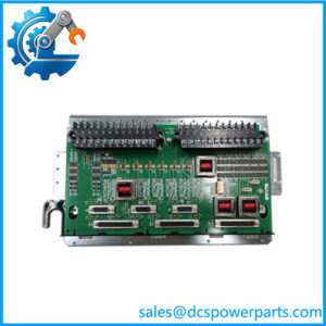
The hardware includes multiple dedicated ribbon-cable interfaces, bayonet connectors, and signal transformers. Documentation also identifies connections between the TCEB, PTBA, TCEA, and TCCB portions of the Mark V architecture. For replacement work, the complete DS200TCEBG1BAA identification matters because Mark V boards were produced in multiple hardware and artwork revisions.
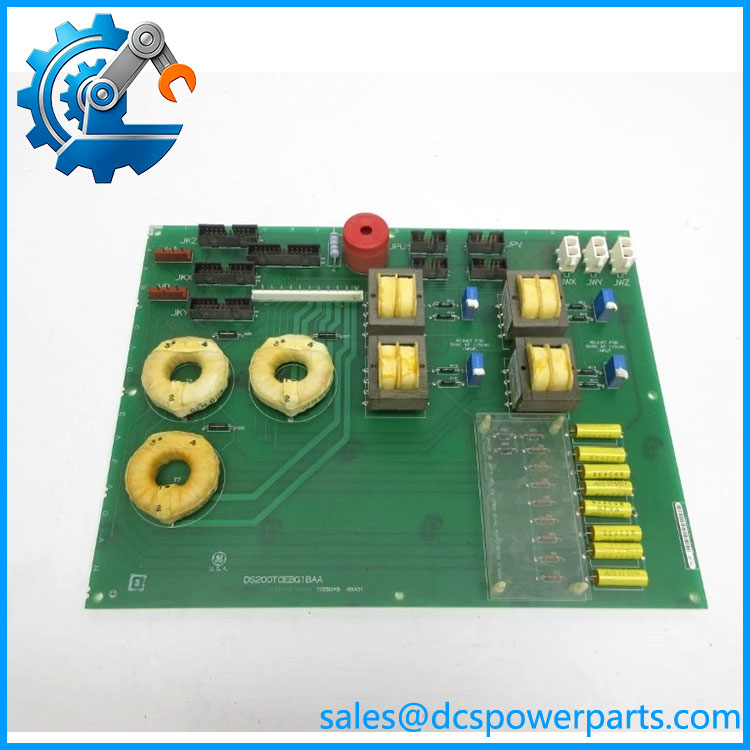
DS200TCEBG1BAA
Application Scenarios & Field Pitfalls — The Engineer’s Perspective
Engineering Pain Point
A TCEB failure can be misleading because the board sits between field termination hardware and downstream Mark V processing boards. A problem reported as an abnormal PT/CT value, synchronization-related signal issue, flame-detection path problem, or unexpected protective-core indication does not automatically prove that the TCEB itself is defective. The PTBA wiring, ribbon cables, mating boards, signal transformers, grounding, and associated Mark V configuration all need to be considered before replacing the PCB.
Typical Applications
- Generator and bus voltage interfacing: The TCEB participates in scaling PT signals used by the Mark V control architecture.
- Generator current signal paths: CT signals associated with the TCCB circuitry pass through the TCEB signal interface.
- Turbine protection systems: Used within Mark V protective-core architectures on compatible gas and steam turbine installations.
- Mark V maintenance and board replacement: Suitable for applications where the installed board is specifically identified as DS200TCEBG1BAA.
Technical Pitfalls to Avoid
- Do not treat it as a generic analog I/O board. Its function is tied to the Mark V protective-core architecture and specific PT/CT signal paths.
- Verify the complete part number. DS200TCEBG1BAA contains functional and artwork revision information. A DS200TCEB board with another suffix should not be assumed to be electrically equivalent simply because the base TCEB designation matches.
- Trace the signal path before condemning the board. The Mark V documentation shows the TCEB in the path between PTBA-related signals and other control boards. Ribbon-cable connections and termination hardware therefore deserve inspection during troubleshooting.
- Label ribbon cables before removal. The board uses several 20-pin and other multi-pin connectors. Misplaced ribbon cables can create secondary faults after maintenance. Field documentation specifically recommends identifying the cables before disconnection.
- Do not copy generic temperature or power ratings from reseller listings into a commissioning specification. Public secondary sources give conflicting values for supply and environmental limits. The installed Mark V cabinet documentation and GE documentation should control those values.
- Check the host Mark V configuration. The board is hardware-specific. Confirm core location, mating boards, terminal-board arrangement, and cable routing before ordering a replacement.
Related Products
- DS200TCEBG1 — Base TCEB Protective Termination Expander Board designation. It provides the functional reference for the DS200TCEB family, but the complete installed suffix must be checked before substitution.
- DS200TCEA — Emergency Overspeed Board used elsewhere in the Mark V protective architecture; it is not a substitute for the TCEB.
- DS200TCCB — Common Extended Analog I/O Board; the TCEB scales PT/CT signals used by this board in the documented architecture.
- DS200PTBA — Protection Termination Module/Board associated with field protection signals that interface through the TCEB.
- DS200TCTG — Turbine Trip Board forming another part of the Mark V protection architecture.
- DS200TCPD — Mark V Power Distribution Board; it performs a different power-distribution function and should not be confused with the TCEB.
- DS200TCPS — Mark V Power Supply Board; it is part of the controller power architecture rather than the TCEB signal-scaling function.
- DS200TCRA — Relay Output Board for Mark V control functions; functionally different from the TCEB.
Procurement and Replacement Note
For a replacement GE DS200TCEBG1BAA, specify the complete part number rather than ordering only a “TCEB board.” Before installation, compare the board label, functional revisions, artwork revision, connector population, and installed Mark V cabinet documentation. The safest replacement decision is based on the exact failed-board identification and the host controller’s hardware configuration, not simply on the shared DS200TCEB family name.
For a field replacement, retain the original board and cable identification until signal continuity and system operation have been verified. If the installed equipment uses a different DS200TCEB suffix, confirm equivalence against the applicable GE documentation before making the substitution.