Description
Product Introduction
Drive faults involving unstable control power, blown fuses, or incorrect motor feedback signals can require inspection of both the power circuitry and instrumentation interface. The GE DS200SDCIG2AHB is an SDCI DC power supply and instrumentation board used in GE DC2000 drive equipment. It combines several supply circuits with signal-conditioning and monitoring functions associated with drive operation.
For maintenance engineers supporting legacy drive cabinets, selecting the correct revision is essential. Check the installed board’s complete part number, jumper positions, switch settings, fuse ratings, and drive wiring before installing a replacement. The applicable GE replacement procedure is identified as manual GEI-100173.
Key Technical Specifications
| Parameter | Specification |
|---|---|
| Model | DS200SDCIG2AHB |
| Manufacturer | General Electric |
| Functional acronym | SDCI |
| Product type | DC power supply and instrumentation board |
| Product family | DS200 / DC2000 drive hardware |
| Application | Compatible GE DC2000 drive systems |
| Logic power circuit | +5 VDC, 4 A |
| Analog supply circuits | +15 VDC and −15 VDC, 0.4 A each, as documented for the board family |
| Other DC supply circuits | ±24 VDC; verify individual ratings in the applicable manual |
| AC supply circuit | 115 VAC, 0.4 A, as documented for the board family |
| Instrumentation functions | AC-line and DC-motor voltage/current monitoring and related signal interfaces |
| Motor-control functions | Field power and armature SCR-gate driver circuitry, depending on drive configuration |
| Hardware adjustments | JP1, JP2, and SW1 |
| Protection | Multiple fuses with blown-fuse indicators |
| Input drive voltage class | Associated with DC2000 drives rated for input voltages up to 600 VAC; this is not the board’s direct supply specification |
| Reference manual | GEI-100173 |
| Operating temperature | Verify from the applicable manufacturer documentation |
| Mounting | Drive-cabinet PCB installation; confirm the original slot and mounting arrangement |
| Lifecycle | Legacy hardware; current availability and condition require confirmation |
The power-circuit details are documented for the SDCI board family. Exact ratings and hardware settings should be checked against GEI-100173 and the installed drive configuration rather than inferred from a similar revision.
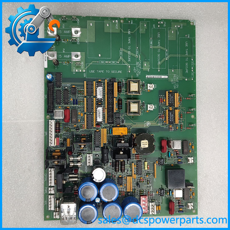
IS200TDBTH6ACD
Application Scenarios and Pain Points
A DC drive may exhibit control-power loss, unexpected trips, or inconsistent feedback when a supply circuit, fuse, or instrumentation path fails. Replacing the SDCI board without checking these surrounding circuits can leave the original fault unresolved.
- DC2000 drive maintenance: Replace a defective power supply and instrumentation PCB in a compatible drive cabinet.
- Motor feedback troubleshooting: Investigate abnormal armature-current, voltage, or field-related signals.
- Power-circuit diagnostics: Check the relevant supply rails, fuses, and associated circuitry when control power is missing.
- Scheduled outage maintenance: Identify the correct board revision and record hardware settings before exchanging the assembly.
Field note: A blown fuse may indicate a downstream short or component fault rather than a failed fuse alone. Investigate the affected circuit before installing a new fuse or replacement board.
Related Products
These models are related to GE drive hardware but should not be treated as automatic substitutes.
| Model | Relationship |
|---|---|
| DS200SDCIG2A | Related SDCI DC power supply and instrumentation board designation documented under GEI-100173. Compare all revision suffixes before substitution. |
| DS200SDCIG2ABA | Related G2 SDCI variant; verify functional revision, coating, and external-exciter configuration. |
| DS200SDCIG2AFB | Another G2 SDCI designation listed in GE drive-hardware inventories. Exact interchangeability is not established by the model similarity alone. |
| DS200SDCIG1AHB | Related SDCI board with a different group designation. Confirm the drive configuration and approved replacement cross-reference. |
| DS200DCFBG1BJB | Separate DC feedback/power supply board used in other GE drive configurations; its functions and connections differ from the SDCI board. |
Engineer’s Guide: Three Checks Before Replacement
- Match the full part number and revision. Record
DS200SDCIG2AHBexactly, including every suffix. Confirm whether the installed drive uses this revision or an approved replacement. - Record the original hardware settings. Document JP1, JP2, and SW1 positions before removal. These settings relate to drive control-source selection, AC contactor dropout timing, and current-transformer burden selection. Use the applicable manual to establish the correct positions.
- Inspect power and instrumentation circuits. Follow the drive’s isolation procedure, verify that stored energy has discharged, and check the relevant fuses and downstream circuits. After replacement, validate supply rails, feedback signals, and drive diagnostics before returning equipment to operation.
Frequently Asked Questions
Q1. What is the GE DS200SDCIG2AHB?
It is a GE SDCI DC power supply and instrumentation board associated with DC2000 drive hardware.
Q2. Does this board belong to the Mark V family?
It is cataloged within the DS200 hardware family and is associated with GE drive systems. Confirm the exact installed equipment and application rather than assuming every DS200 board is a turbine controller.
Q3. What power outputs does DS200SDCIG2AHB provide?
The documented SDCI circuit family includes +5 VDC, ±15 VDC, ±24 VDC, and 115 VAC supply circuits. Confirm each output’s rating and use from the applicable manual.
Q4. What are JP1, JP2, and SW1 used for?
They are configurable hardware elements associated with drive control-source selection, AC contactor dropout timing, and AC-line current-transformer burden selection. Their positions must match the drive application.
Q5. Can DS200SDCIG2A replace DS200SDCIG2AHB?
Do not assume direct interchangeability. Compare the complete catalog numbers, functional revisions, hardware settings, and approved replacement documentation for the specific drive.
Q6. What should I request when purchasing a refurbished board?
Request clear label and component photographs, revision information, inspection records, functional test results, and written warranty terms. Ask which supply circuits and instrumentation functions were actually tested.
Q7. What manual should be used for replacement?
The product documentation identifies GEI-100173 as the replacement-procedure manual for the SDCI DC power supply and instrumentation board. Confirm that the copy matches the installed hardware and follow the site’s electrical safety procedures.
Procurement recommendation: For , prioritize exact revision matching, documented hardware settings, and evidence of functional testing. Because this board combines power and instrumentation functions, physical fit alone is not sufficient to establish compatibility.