Description
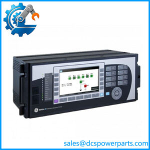
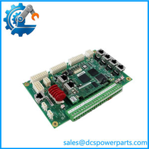
GE DS200SDCCG4AGD | Mark V SDCC Drive Control Card
Key Technical Specifications
| Parameter | Specification |
|---|---|
| Manufacturer | General Electric |
| Series | Mark V Speedtronic |
| Model | DS200SDCCG4AGD |
| Functional Acronym | SDCC |
| Product Type | Drive Control Card |
| Primary Role | Drive control and monitoring |
| Application | Mark V / TC2000 drive systems |
| Microprocessors | 3 |
| Memory Architecture | Shared RAM accessible by multiple processors |
| Diagnostic LEDs | 10 |
| Power-Supply Interface | 2 board connections |
| Test Point | P15 — regulated +15 V supply |
| Functional Revision 1 | A |
| Functional Revision 2 | G |
| Artwork Revision | D |
| PCB Coating | Normal coating |
| Instruction Manual | GEI-100029 |
| Firmware | Board/application dependent; verify installed revision |
| Control Supply | Verify against cabinet documentation |
| Operating Temperature | Verify against applicable GE documentation |
| Mounting | Mark V card rack / drive-control cabinet |
The SDCC uses three processors that divide control and monitoring functions, with shared RAM allowing the processors to exchange information. The board also provides interfaces to optional cards and other drive-control hardware.
The DS200SDCCG4AGD is specifically associated with the G4 SDCC configuration. Available technical references state that the G4 version differs from earlier G1A SDCC boards in its expanded EE parameter-storage area and firmware. That distinction is important when evaluating an apparently similar SDCC as a replacement.
Product Introduction
The GE DS200SDCCG4AGD is a Drive Control Card used in GE Mark V Speedtronic drive and TC2000 turbine-control applications. The SDCC is a central processing board rather than a simple I/O interface. It executes drive-control functions, exchanges data with associated hardware, monitors operating conditions, and provides diagnostic information through its onboard LED array.
The board’s three-processor architecture and shared-memory design are particularly relevant during troubleshooting. A communication, parameter, or drive-control problem can originate in the SDCC itself, its power-supply interface, connected option cards, firmware/parameter storage, or another board in the control chain. Replacing the SDCC without preserving the installed configuration can therefore create a second problem while attempting to correct the first.
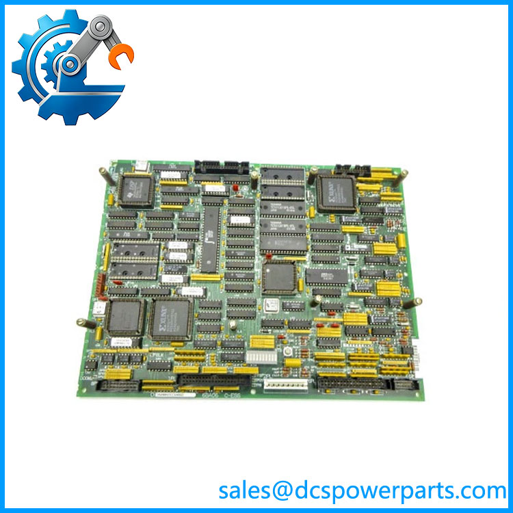
DS200SDCCG4AGD
Engineering Pain Point
SDCC faults often appear as broad drive-control failures because this board participates in several control and diagnostic functions. If the drive will not initialize, produces unexpected diagnostic codes, or loses communication with associated boards, first determine whether the fault is local to the SDCC, its power supply, or the connected control architecture. The onboard LED sequence and the stored drive parameters can provide useful evidence before board replacement.
Typical Applications
- GE Mark V drive control: Central processing for applicable Mark V drive assemblies.
- TC2000 turbine applications: The G4 SDCC configuration is documented for TC2000 turbine systems.
- Drive monitoring and diagnostics: The 10-LED diagnostic array provides operating indications and coded fault information.
- Power-stage coordination: Interfaces with the Power Supply Interface Board and other Mark V control hardware.
Technical Pitfalls to Avoid
- Do not treat SDCC as a generic PLC CPU. Its firmware, memory organization, interfaces, and parameters are tied to the Mark V drive architecture.
- Match the complete part number. The distinction between DS200SDCCG4AGD, other G4 revisions, and G1A-family SDCC boards is significant. Do not approve a substitute from the SDCC acronym alone.
- Verify firmware and EE parameter storage. The G4 configuration is documented as having an enlarged EE parameter-storage area and different firmware from G1A SDCC versions. A physically similar board may not contain the required application configuration.
- Record the LED fault sequence. The board’s 10 LEDs are used for operating indication and coded diagnostics. Capture the sequence before removing a failed board whenever system conditions allow.
- Check the power-supply interface first. The SDCC connects to the Power Supply Interface Board through two dedicated connections. A missing or abnormal control supply can mimic an SDCC hardware failure.
- Check P15 during controlled troubleshooting. P15 is identified as the regulated +15 V power-supply test point. Use the applicable GE maintenance procedure and electrical safety controls when measuring live equipment.
- Do not copy generic temperature or voltage specifications from reseller listings. The available references do not provide a sufficiently consistent exact-board specification for these limits. Use the applicable Mark V cabinet drawings and GE documentation.
Related Products
- DS200SDCCG4A — Base G4 SDCC Drive Control Card designation; the complete revision and artwork suffix must be checked before substitution.
- DS200SDCCG4AEC — G4 SDCC configuration with A/E functional revision and C artwork revision; function is related, but the complete revision is different.
- DS200SDCCG1A — Earlier SDCC family; G1A and G4 configurations should not be assumed interchangeable because of firmware and parameter-storage differences.
- DS200IMCPG1CCB — IMCP IGBT power-supply interface board associated with Mark V drive-control hardware; it serves a different function from the SDCC.
- DS200SLCCG3AGH — SLCC LAN Communication Board; provides communication processing rather than the primary SDCC drive-control function.
- DS200TCEBG1BAA — TCEB Protective Termination Board used in other Mark V protection/signal paths.
- DS200TCQAG1BHF — TCQA Analog I/O Board; handles analog signal processing rather than SDCC drive control.
- DS200TCCBG1BED — TCCB Common Extended Analog I/O Board used elsewhere in the Mark V signal architecture.
- DS200TCPDG1BDC — TCPD Power Distribution Board; provides power distribution rather than drive-control processing.
Procurement and Replacement Note
For DS200SDCCG4AGD, procurement should specify the , including the A/G functional revisions and D artwork revision. Record the existing board’s EPROM/firmware identification, parameter-storage configuration, jumper settings, connector arrangement, and diagnostic LED condition before removal.
The G4 configuration deserves particular attention because available documentation identifies differences from G1A SDCC boards in firmware and EE parameter storage. Do not treat a board as a drop-in replacement simply because it is labeled SDCC or DS200SDCCG4. Verify the host drive, Mark V application, firmware, stored parameters, and complete hardware revision against the installed system documentation.