Description
GE DS200DTBAG1AAA | Mark V Digital Contact Input Termination Board
Key Technical Specifications
| Parameter | Specification |
|---|---|
| Manufacturer | General Electric |
| Series | Mark V Speedtronic |
| Model | DS200DTBAG1AAA |
| Functional Acronym | DTBA |
| Product Type | Digital Contact Input Termination Board |
| Primary Function | Contact-input field termination |
| Terminal Blocks | 2 |
| Maximum Field Wiring | Up to 95 wires per published board documentation |
| Maximum Terminal Wiring | Up to approximately 190 wire connections across both terminal blocks |
| Manual Jumpers | 5 |
| Jumper Designations | BJ1–BJ5 |
| 2-Pin Connectors | 2 |
| Mark V Connections | J12, JQR, JQS/T, JY |
| Associated Digital I/O | TCDA-related architecture |
| Contact Inputs | First 46 contact inputs are documented in the DTBA/TCDA path for applicable Mark V LM configurations |
| Interrogation Voltage | Mark V architecture may use 24 VDC or 125 VDC depending on system configuration |
| PCB Coating | Normal coating |
| Assembly | Normal assembly |
| Firmware | Not independently programmable |
| Operating Temperature | Verify against the applicable Mark V cabinet documentation |
| Mounting | Mark V control cabinet / digital I/O installation |
The DTBA is a termination layer rather than the processor responsible for interpreting the contact states. In documented Mark V LM configurations, the first 46 contact inputs in the digital core are connected through DTBA to the TCDA board, where the contact inputs are optically isolated and processed. The exact excitation arrangement can be either 24 VDC or 125 VDC depending on the installed Mark V configuration.
The board contains two large terminal blocks, five jumpers, and two 2-pin connectors. The published connection designations are J12, JQR, JQS/T, and JY. JQS/T is described as an available connection that is used less frequently than the other interfaces.
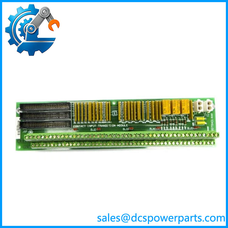
DS200DTBAG1AAA
Product Introduction
The GE DS200DTBAG1AAA is a DTBA Digital Contact Input Termination Board used in GE Mark V Speedtronic turbine control systems. Its primary job is to provide the field wiring termination layer for discrete contact signals before those signals reach the Mark V digital input electronics. Typical signals can originate from switches, relays, interlocks, permissives, and other turbine auxiliary devices.
The board is passive in its basic termination role, but its jumper configuration and connection to the Mark V digital-core architecture matter during troubleshooting and replacement. It should not be treated as a standalone 24 VDC PLC input card. The actual contact excitation voltage and signal interpretation depend on the associated Mark V cabinet configuration and TCDA circuitry.
Engineering Pain Point
A DTBA fault can be confused with a failed field switch or TCDA input because the board sits between field wiring and the digital input electronics. When multiple contact indications fail simultaneously, inspect the common termination board, excitation source, wiring, jumpers, and downstream TCDA connections before replacing individual field devices.
Typical Applications
- Turbine contact inputs: Terminates discrete field contacts used by GE Mark V turbine controls.
- Digital-core input interface: Provides the wiring interface between field contact circuits and TCDA-related digital input processing.
- Turbine interlocks and permissives: Handles discrete status signals associated with turbine operating logic.
- Auxiliary equipment monitoring: Interfaces selected contact signals from valves, switches, relays, and turbine auxiliary equipment.
Technical Pitfalls to Avoid
- Do not classify it as a generic PLC DI card. The DS200DTBAG1AAA is a Mark V-specific termination board. The downstream TCDA performs the digital input processing in the documented architecture.
- Verify the excitation voltage. Published Mark V documentation indicates that contact-input excitation can be configured around 24 VDC or 125 VDC depending on the system implementation. Do not assume that every DTBA installation uses 24 VDC.
- Record BJ1–BJ5 before removal. The five jumpers are part of the board’s contact-input isolation/testing arrangement. Their positions should be documented before disturbing the board.
- Label every field wire. With two terminal blocks accommodating a large number of field connections, a single misplaced wire can create several unrelated-looking digital alarms after replacement.
- Check the TCDA relationship. A missing or incorrect contact indication does not automatically mean the DTBA has failed. Check the complete path from field contact → DTBA → TCDA → Mark V configuration.
- Do not assume JQS/T is required. The connection is present on the board but is described as being used less frequently. Confirm its actual use from the cabinet wiring documentation.
- Handle the board by its edges. The large number of terminals, jumpers, and connectors makes mechanical damage during removal a realistic maintenance risk. Published replacement guidance specifically recommends careful handling and avoiding contact with board components.
Related Products
- DS200DTBAG1A — Earlier DTBA Digital Contact Terminal Board designation; related function, but the complete revision must be compared before substitution.
- TCDA — Mark V Digital Contact Input Board associated with processing the contact signals terminated through DTBA.
- DTBB — Related Mark V digital contact termination board used for other contact-input groups.
- DS200TBCA — Related Mark V termination-board family; signal type and cabinet position must be verified before substitution.
- DS200TBCB — Analog termination board family; handles a different signal class from DTBA.
- DS200TCQAG1BHF — TCQA analog I/O board; not a substitute for the digital contact termination function.
- DS200TCEAG1BTF — TCEA Emergency Overspeed Board; protection function is different from DTBA.
- DS200TCCBG1BED — TCCB Common Extended Analog I/O Board; operates elsewhere in the Mark V I/O architecture.
Procurement and Replacement Note
For DS200DTBAG1AAA, specify the complete GE part number, not merely “DTBA.” Before removing the existing board, photograph the terminal blocks, jumper positions, connector locations, and board revision markings. Confirm the associated TCDA board and the actual contact-excitation arrangement in the cabinet.
The 24 VDC / 125 VDC distinction is especially important. Published Mark V references show that the interrogation voltage depends on the system configuration, so a generic product listing stating one universal voltage should not be used as the final wiring reference. Verify the cabinet drawings and installed board configuration before energization.