Description
Product Overview
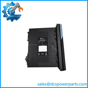
The GE DS200FCSAG2A is a current-sensing feedback board associated with General Electric’s LS2100 static starter control system. Installed in the static starter power conversion cabinet, it participates in current-signal feedback for AC drive and power-conversion applications used with gas turbine generator systems. The board is identified by the functional abbreviation FCSA, and its role is tied to the sensing interface rather than general-purpose PLC logic execution. Correct identification matters because similarly numbered GE circuit boards can perform entirely different functions.
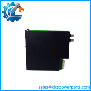
Within an LS2100 installation, current feedback is important to power-conversion control and the supervision of electrical operating conditions. The DS200FCSAG2A works as part of a larger assembly, so its suitability depends on the installed hardware configuration, associated control-power connections, and the applicable wiring documentation. Product references identify a three-pin LEMPS connector and a 12-pin connector; these physical details are useful when checking a replacement against the removed board. Do not assume that matching the DS200 prefix alone establishes interchangeability.
For maintenance teams supporting aging turbine-starting equipment, the GE DS200FCSAG2A can be relevant to fault recovery, planned component replacement, and critical-spares inventory. Before procurement, compare the complete part number, board revision, connector layout, and mounting arrangement against the installed assembly. The available documentation references include the LS2100 installation and startup guide GEH-6678 and parts manual GEI-100222. To be completely transparent, the precise electrical ratings and acceptance limits should come from the applicable OEM documentation—not from assumptions based on another board in the DS200 family.
Key Technical Specifications
| Parameter | Value |
|---|---|
| Manufacturer | General Electric (GE) |
| Full Model Number | DS200FCSAG2A |
| Product Type | Current-Sensing Feedback Board |
| Functional Abbreviation | FCSA |
| Product Series | LS2100 Static Starter Control |
| Installation Location | Static Starter Power Conversion Cabinet |
| Primary Application | AC drive and power-conversion systems for turbine-generator starting |
| Three-Pin Connector | LEMPS |
| Additional Connector | 12-pin connector; verify labeling and pinout on the installed board |
| Installation Documentation | GEH-6678 |
| Parts Documentation | GEI-100222 |
| Operating Voltage | Confirm from the applicable OEM wiring and installation documentation |
| Communication Protocol | No conventional network protocol verified for this board |
| Operating Temperature | Confirm from the applicable OEM specification |
| Protection Rating | Not verified; this is a cabinet-mounted circuit board |
| Condition | Must be confirmed at quotation or order stage |
Specifications and application details are based on available product references; unverified electrical ratings are deliberately omitted rather than estimated.
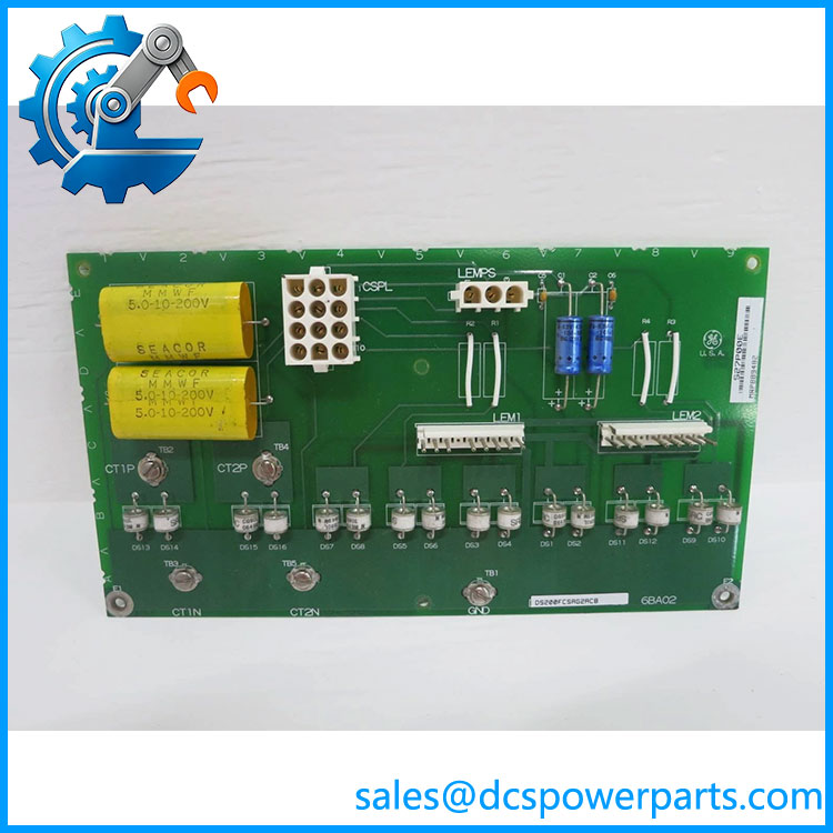
DS200FCSAG2A
Related Products
The following references are relevant when checking replacement options or planning maintenance. Similar part numbers do not establish interchangeability.
- DS200FCSAG1A — An earlier FCSA board designation referenced in LS2100 documentation discussions. Compare the complete revision, circuit configuration, and approved parts list before considering it as a substitute for DS200FCSAG2A.
- DS200FCSAG2ACB — A fuller revision designation reported for the DS200FCSAG2A board family. Confirm whether the suffix identifies the exact assembly revision required by your equipment; do not assume every revision is interchangeable.
- LS2100 Static Starter Control System — The associated control platform. Use its system documentation to establish the correct board location, wiring, and approved replacement configuration.
- GEH-6678 — installation and startup documentation. This is a technical reference rather than a replacement component; consult the applicable revision for installation and commissioning requirements.
- GEI-100222 — Parts documentation identified for the FCSA board. Use it to cross-check part identification and assembly requirements before ordering.
- GEI-100476 — ControlST documentation cited in connection with board identification. Confirm document applicability to the installed system generation before using it to approve a substitution.
- Control Power Supply (CPS) — An associated subsystem that supplies power to the FCSA board. Verify the actual installed supply, connector assignments, and required voltage levels using the applicable wiring documentation.
- Static Starter Power Conversion Cabinet — The cabinet assembly in which the board is installed. Its wiring, mounting, and connected power-conversion hardware determine the practical replacement requirements.
Frequently Asked Questions (FAQ)
1. Is the GE compatible with every GE Mark V or system?
No universal compatibility should be assumed. The is documented in connection with the static starter platform. Before installation, check the equipment model, board revision, cabinet assembly, and applicable parts list. A shared manufacturer or DS200 prefix is not sufficient evidence of compatibility.
2. Can I hot-swap the while the turbine starter is running?
Do not assume hot-swapping is permitted. This board is installed in a power-conversion cabinet, and its associated circuits may carry hazardous voltages or stored energy.
Before replacement:
- Follow the plant’s approved shutdown and lockout/tagout procedures.
- Isolate the applicable power sources and verify the absence of hazardous voltage.
- Follow the OEM discharge, removal, and installation instructions.
- Complete the required inspection and functional checks before returning the equipment to service.
Only use a live-replacement procedure if the OEM explicitly authorizes it for the exact assembly and operating conditions.
3. Does the support firmware version 3.1?
A standalone firmware compatibility claim cannot be confirmed from the available board identification information. The is a current-sensing feedback board, not a general-purpose PLC CPU.
To assess compatibility, establish which controller and software version are installed, then check the relevant documentation for hardware revision requirements. Do not apply a firmware compatibility statement from an unrelated GE controller.
4. Will replacing the erase my control logic?
The board is identified as a current-sensing feedback board, not the primary controller that stores application logic. Replacing it therefore should not be treated as a controller-programming operation.
However, the replacement can affect system operation if its revision, wiring, or signal characteristics do not match the installed configuration. Before work begins, preserve relevant controller backups and configuration records, document existing connections, and follow the OEM recommissioning procedure.
5. How can I verify that a new-surplus is authentic?
A new-surplus description alone does not establish authenticity or operating condition. Request the following evidence from the supplier:
- Clear photographs of the complete board and its identification labels.
- Confirmation of the full part number and any revision suffix.
- Inspection records covering connector condition, corrosion, damaged components, and evidence of rework.
- A written statement of condition and the applicable warranty terms.
- Functional test documentation, where testing is supported and appropriate for the board.
Factory packaging can help with traceability, but it does not independently prove that a board is genuine or functional.
6. What should I check before ordering a replacement?
Use this checklist to reduce the risk of ordering an incompatible board.
When the original board is available, its identification label and physical layout are often the most useful starting points.
7. What warranty should I expect for the GE ?
Warranty coverage depends on the supplier, product condition, and sales agreement. New-surplus, refurbished, and used boards should not be assumed to carry equivalent coverage.
Before placing an order, request written confirmation of the warranty period, what constitutes a covered failure, whether testing is documented, and how a return or replacement claim is handled. For critical turbine-starting equipment, these details should be settled before the spare is needed during an outage.