Description
GE DS200DTBDG1ABB Contact Output Expansion Termination Module
Product Introduction
The GE DS200DTBDG1ABB is a Contact Output Expansion Termination Module used within the GE Mark V Speedtronic turbine control architecture. The DTBD is a termination/interface board rather than a standalone PLC CPU, analog acquisition module, or network controller. Its role is to organize contact-output and associated field wiring between Mark V control hardware and the equipment-side circuits. This distinction matters during replacement because the board’s function depends heavily on its connected terminal wiring, companion boards, and the specific Mark V cabinet design.
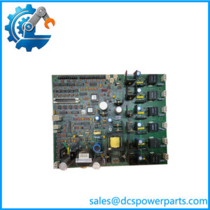
The GE DS200DTBDG1ABB has two terminal blocks, with 107 signal-wire terminals documented for each block. The board also carries three 34-pin connectors, three 40-pin connectors, multiple test points, and two hardware jumpers. Connector references documented for the DTBD include JS1–JS8 for TCRA relay signals, J8 for TCPD solenoid power, and J19/J20 for daisy-chained contact-output power connections. These interfaces make the board part of a larger Mark V output and termination architecture rather than an independently configurable I/O station.
For procurement, the complete GE DS200DTBDG1ABB identifier should be matched before replacement. The final suffix identifies a specific hardware configuration, and DTBD-family boards should not be substituted solely because the base acronym is the same. Mark V cabinet drawings, connector assignments, jumper positions, upstream TCRA/TCPD hardware, and the actual field-output circuits should all be checked before returning a replacement board to service.
Technical Specifications
| Parameter | Specification |
|---|---|
| Product Model | DS200DTBDG1ABB |
| Manufacturer | General Electric (GE) |
| Product Series | Mark V / DS200 Speedtronic |
| Functional Acronym | DTBD |
| Product Type | Contact Output Expansion Termination Module / Terminal Board |
| Primary Function | Contact-output expansion and field termination |
| Terminal Blocks | 2 |
| Signal Terminals | 107 per terminal block |
| 34-Pin Connectors | 3 |
| 40-Pin Connectors | 3 |
| Hardware Jumpers | 2 |
| Test Points | Multiple |
| Connector References | JS1–JS8, J8, J19, J20 |
| PCB Coating | Normal coating |
| Mark V Series Grouping | Group 1 |
| Assembly Type | Normal assembly |
| Board Dimensions | Approximately 11.25 × 3 in. |
| Communication Protocol | No standalone communication protocol established |
| Working Voltage | Application-dependent; verify cabinet drawings |
| Output Voltage | Application-dependent; do not assume a universal output rating |
| Operating Temperature | Not reliably established for the bare board |
| Protection Rating | Not independently established |
| Operating Accuracy | Not applicable as a standalone measurement module |
The connector and terminal information above is consistently reported in technical records for the exact DS200DTBDG1ABB.
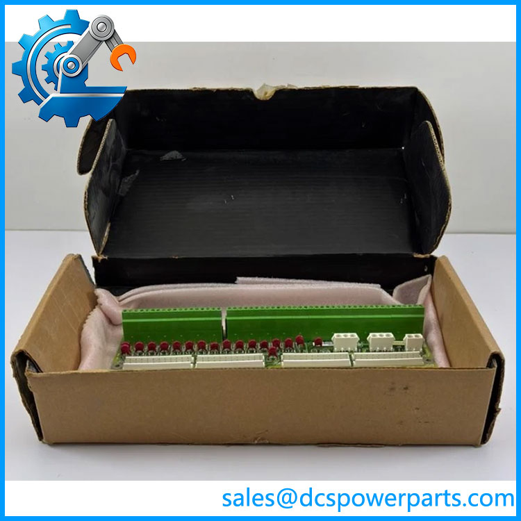
DS200DTBDG1ABB
Main Features and Engineering Considerations
High-Density Field Termination
The primary engineering characteristic of the is its high-density termination arrangement. Two terminal blocks provide 107 signal-wire positions each, giving the board a substantial field-wiring interface within the Mark V cabinet. This makes accurate terminal identification particularly important during maintenance. A replacement should be wired against the approved cabinet drawing rather than by copying the general-purpose pinout of another DTBD board.
Contact-Output Expansion
The DTBD is documented as a contact-output expansion termination module. Some records specifically identify its connections to TCRA relay-signal circuitry and TCPD solenoid-power circuitry. J19 and J20 are associated with daisy-chained contact-output power connections. These relationships should be treated as architecture-specific: they do not mean every DTBD installation has identical field loads or identical wiring.
Jumper and Connector Verification
Two hardware jumpers are present on the board. Their installed positions should be documented before removal. The same applies to the three 34-pin and three 40-pin connectors. Connector population can vary with the cabinet application, so an empty connector on an original board should not automatically be populated on a replacement.
Do Not Treat It as Analog I/O
A few current listings describe this part with generic voltage/current specifications or even processor and memory characteristics. Those claims are not supported by the stronger DTBD-specific records. The more defensible classification is a Mark V terminal/contact-output expansion board.
Legacy System Considerations
Mark V is a legacy turbine-control platform. The practical replacement issue is therefore not only whether a board appears physically identical. Hardware revision, cabinet architecture, companion boards, terminal wiring, and configuration must all agree. GE migration documentation can also distinguish installed Mark V hardware from later Mark VIe migration configurations, so migration compatibility should be checked separately from simple replacement compatibility.
Application Scenarios
- GE Mark V gas turbine control systems
- GE Mark V steam turbine control systems
- Mark V turbine auxiliary-control circuits
- Contact-output termination
- Relay and solenoid field wiring
- Mark V cabinet refurbishment
- Legacy turbine-control maintenance
- Replacement of installed DTBD terminal boards
- Controlled Mark V-to-newer-platform migration projects
Engineer’s Guide: Field Pitfalls
1. Do not confuse terminal-board function with I/O processing.
The DTBD is an interface and termination board. Do not assign analog conversion, CPU, memory, or network functions to it without cabinet-specific documentation.
2. Verify all 214 terminal positions.
Two blocks with 107 terminals each create considerable opportunity for a wiring mistake. Terminal numbers should be checked against the actual Mark V drawing.
3. Record the two jumper positions.
Do this before removing the original board. Jumper configuration should be preserved unless an approved engineering change specifies otherwise.
4. Check connector population.
The board has three 34-pin and three 40-pin connectors, but not every cabinet necessarily uses every interface. Compare the installed board with the replacement before reconnecting cables.
5. Identify the companion hardware.
References to TCRA relay signals and TCPD solenoid power make the upstream/downstream architecture important. A DTBD board should not be evaluated in isolation.
6. Do not transfer ratings from another DTBD suffix.
The full identifier is the procurement reference. Similar DTBD boards may have different circuit arrangements.
7. Inspect the physical board before installation.
Check terminal blocks, connectors, jumper hardware, board coating, mounting points, and signs of contamination or previous repair.
Frequently Asked Questions
What is GE ?
It is a GE Mark V Contact Output Expansion Termination Module, also described as a DTBD terminal board.
What does DTBD stand for in this application?
DTBD is the functional acronym associated with this Mark V terminal-board family. The exact board is identified by the complete ordering number.
How many terminals does have?
The board is documented with two terminal blocks, each containing 107 signal-wire terminals.
How many connectors are on the board?
Technical records identify three 34-pin connectors and three 40-pin connectors, along with multiple other connector references associated with the Mark V installation.
Is an analog input module?
No. The stronger identification is a contact-output expansion termination module / terminal board. It should not be marketed or engineered as a conventional analog input card.
Does it have Ethernet or another communication protocol?
No standalone Ethernet or fieldbus function has been reliably established for this board. Its documented role is physical signal termination and interface within the Mark V architecture.
What should be checked before purchasing a replacement?
Confirm the complete part number, hardware revision, terminal-board position, jumper settings, connector population, associated TCRA/TCPD hardware, cabinet drawings, and actual field wiring.
Procurement Note
For a critical Mark V replacement, request photographs showing the complete nameplate, board revision, terminal blocks, connectors, jumpers, and PCB condition. Do not accept “DTBD equivalent” as sufficient identification. The exact suffix and installed configuration should match the turbine’s engineering documentation.
For refurbished inventory, functional inspection should include connector integrity, terminal condition, jumper verification, continuity checks where applicable, and a documented test against the intended Mark V configuration before installation.