Description
Product Introduction
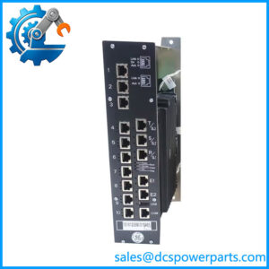
A drive that loses its control-level supply or develops unreliable voltage-feedback signals can trigger faults that are difficult to distinguish from problems in the power stage. The GE DS200DCFBG1BJB combines power-supply circuitry with feedback and monitoring functions used in compatible GE drive systems.
When sourcing this board, match the complete DS200DCFBG1BJB number and the installed jumper and DIP-switch settings. The correct replacement must suit the drive application and board revision; a unit that fits the carrier may still require configuration checks or parameter adjustment before commissioning.
Key Technical Specifications
| Parameter | Specification |
|---|---|
| Manufacturer | General Electric |
| Model | DS200DCFBG1BJB |
| Product family | Mark V / DS200 |
| Functional acronym | DCFB |
| Product type | Power supply and DC feedback board |
| Input power | Documented DCFB family inputs include 38 VAC and 115 VAC, or a 24 VDC input arrangement, depending on application |
| DC outputs | +5 VDC, ±15 VDC, and ±24 VDC supply rails |
| Auxiliary AC output | Fused 115 VAC output for enclosure fans in applicable drive configurations |
| Feedback functions | Voltage/current feedback and AC-line monitoring circuits, depending on application |
| Jumper configuration | JP1–JP12; additional jumper arrangements may apply to later revisions |
| DIP switches | Seven switch banks for application-specific settings |
| Protection | Three onboard fuses are documented for the matching board family |
| Status indicators | Two red LEDs and one neon indicator are described in board documentation |
| Manual reference | GEI-100028C |
| Mounting | Drive board carrier; verify the specific cabinet arrangement |
These are family-level specifications from the DCFB documentation. Confirm the exact input arrangement and output requirements against the equipment schematic and the board’s original configuration before applying power.
Application Scenarios & Pain Points
Power-supply and feedback faults can interrupt drive operation while leaving the underlying cause unclear. Correct board identification and configuration are essential during troubleshooting.
- DC drive maintenance: Restore control-level power distribution when the installed DCFB board is confirmed faulty.
- AC drive systems: Support compatible drive configurations that use the DCFB board for control power and feedback circuits.
- Excitation-system maintenance: Check the application-specific wiring and circuit role before sourcing a replacement for EX2000 equipment.
- Voltage-feedback troubleshooting: Investigate feedback scaling and related signals when drive measurements disagree with expected values.
Field note: an illuminated fuse-status indicator can help narrow a fault, but it does not prove that the board itself is defective. Check the relevant fuse, downstream load, wiring, and supply conditions using the approved maintenance procedure.
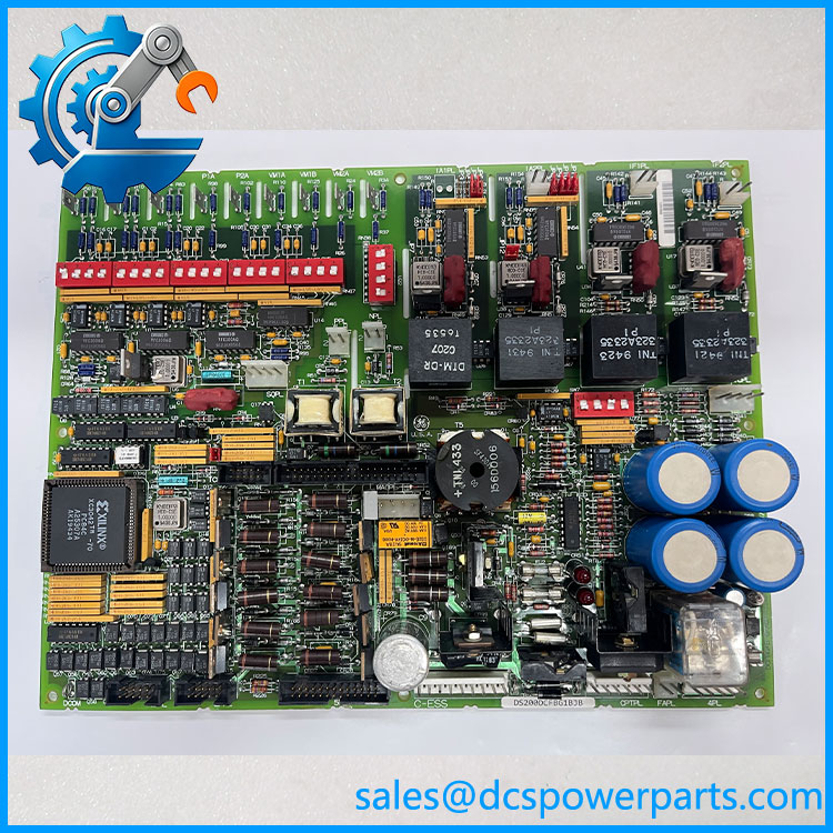
DS200DCFBG1BJB
Related Products
These models are related GE drive-system boards, but they serve different functions or have different configurations.
- DS200DCFBG1B — Closely related DCFB power supply board designation; verify the complete suffix and revision before considering substitution.
- DS200DCFBG1A — Earlier DCFB board variant covered by the DCFB power-supply manual; confirm revision-specific compatibility.
- DS200PCCAG1A — GE drive power-connect board family; a different function from the DCFB supply and feedback board.
- DS200RTBAG1A — GE relay terminal board family; verify the system application and wiring requirements independently.
- DS200SDCCG1A — Drive control board family associated with compatible GE systems; it performs control functions rather than the DCFB board’s power-supply role.
Engineer’s Guide: Three Replacement Checks
1. Record every jumper and DIP-switch setting. Photograph the installed board before removal. Copy settings only after checking the relevant GEI-100028C tables for the specific revision and application.
2. Verify power inputs and feedback wiring. Confirm the control-power transformer arrangement, required DC rails, fan-supply use, and feedback connections against the drive schematic. Do not assume all DCFB installations use the same input source.
3. Check revision compatibility and feedback calibration. GE documentation distinguishes board revisions by their functional and backward-compatibility characteristics. After installation, follow the applicable procedure for voltage-feedback offset adjustment and verify the expected control signals before returning the drive to service.
Frequently Asked Questions
What is the GE DS200DCFBG1BJB used for?
It is a DCFB power supply and feedback board used in compatible GE drive and excitation systems. It supplies control-level power and supports selected voltage/current feedback and monitoring circuits. Its exact role depends on the host application.
Which GE systems use this board?
The DCFB family is documented for AC2000, CB2000, DC2000, EX2000, FC2000, GF2000, and ME2000 applications. Confirm the specific cabinet and application because the board is used differently in some EX2000 systems.
What DC voltages does the board provide?
The documented DCFB family provides +5 VDC, +15 VDC, −15 VDC, +24 VDC, and −24 VDC supply rails. The current capacity and regulation characteristics vary by rail; use the applicable manual for exact electrical limits.
Can DS200DCFBG1BJB replace DS200DCFBG1B?
Do not assume direct interchangeability from the shared base number. Compare the full catalog number, board revision, jumper settings, DIP-switch settings, and application requirements. GE’s manual explicitly emphasizes that all digits matter when ordering or replacing a board.
How should a replacement board be checked?
Inspect the board and connectors, confirm fuse ratings, and compare all configuration settings with the original. After installation, test the supply rails and feedback signals according to the drive manual and site safety procedures.
Is the board available new or refurbished?
Availability and condition depend on the supplier’s current inventory. Request confirmation of the exact suffix, photographs of the supplied unit, test records, warranty terms, and dispatch lead time. Do not equate cleaned or visually inspected stock with fully tested hardware.
What information should I include in a quotation request?
Provide the full model number DS200DCFBG1BJB, the host drive or excitation-system model, the required condition, and photographs of the installed board. Ask the supplier to confirm revision compatibility, testing scope, warranty, and lead time in writing.
Procurement recommendation: Confirm the complete board number and original configuration before ordering. For this DCFB board, correct jumper and DIP-switch settings, power-input arrangement, and feedback calibration are as important as physical fit.