Description
GE 269PLUS-D/O-261-100P-120 — Motor Management Relay
Key Technical Specifications
| Parameter | Specification |
|---|---|
| Product Model | 269PLUS-D/O-261-100P-120 |
| Product Family | GE Multilin 269 Plus |
| Product Type | Motor Management Relay |
| Mounting / Construction | Drawout |
| Application | Three-phase AC motor protection |
| RTD Type | 100 Ω Platinum |
| RTD Option | 100P |
| Control Voltage | 120 VAC / 125 VDC |
| Option Code | 261 |
| Protection Platform | Microprocessor-based |
| Digital Inputs | 5 programmable inputs reported for the 269 Plus configuration |
| Output Relays | 4 |
| Analog Output | 1 programmable analog output |
| RTD Inputs | Up to 12 programmable RTD inputs reported for the 269 Plus |
| Communication | RS-485 / Modbus RTU on applicable configuration |
| Overload Protection | 8 standard overload curves plus programmable/flexible curve capability |
| Thermal Protection | Motor thermal model with RTD monitoring |
| Ground Fault | Supported |
| Phase Protection | Phase imbalance / single-phase protection |
| Locked Rotor | Supported |
| Mechanical Protection | Jam / trip-related protection functions |
| Operating Temperature | -25°C to +60°C |
| Power Consumption | Approx. 20 VA |
| Configuration | Keypad and software configuration |
| Engineering Software | EnerVista 269 |
| Approx. Unit Weight | 2.9 kg |
The 100P portion of the ordering designation is particularly important: available references identify it with 100 Ω platinum RTD inputs. The 269 Plus documentation also describes RTD-based stator and bearing-temperature monitoring alongside current-based motor protection.
Product Introduction
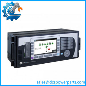
The GE 269PLUS-D/O-261-100P-120 is a microprocessor-based motor management relay designed for protection and monitoring of three-phase AC motors. It combines electrical protection with thermal supervision, allowing the relay to evaluate motor current and temperature information rather than relying only on a conventional overload device. The 269 Plus family includes functions for overloads, ground faults, phase problems, locked rotor, bearing and winding temperature, and multiple-start supervision.
The GE 269PLUS-D/O-261-100P-120 is the drawout 261-option / 100 Ω platinum RTD / 120 VAC-125 VDC configuration. This complete ordering code should be retained when sourcing a replacement. The 269 Plus family contains different RTD and control-power configurations, so a relay that merely carries the “269 Plus” designation is not necessarily a valid replacement.
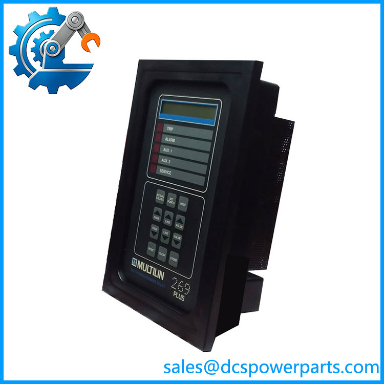
269PLUS-D
Application Scenarios & Field Pitfalls (Engineer’s Perspective)
The 269PLUS-D/O-261-100P-120 is applicable to medium-sized industrial AC motors, motor control centers, pump and fan drives, compressor systems, and other motor-driven equipment where winding and bearing temperature need to be monitored together with electrical loading. Its thermal model and RTD inputs make it particularly useful where motor heating, repeated starts, overload conditions, or mechanical loading are part of the protection study.
Field pitfalls:
- Verify the RTD type. The “100P” designation indicates the 100 Ω platinum RTD configuration. Do not substitute a relay configured for a different RTD material or resistance characteristic.
- Confirm control power. The 120 VAC / 125 VDC designation is part of the exact configuration. Do not assume every 269 Plus accepts the same auxiliary supply.
- Check the option code. The 261 portion should be matched when replacing an installed relay. Different 269 Plus ordering codes can change hardware and functional options.
- Back up protection settings. Record overload curves, motor full-load current, CT ratios, start characteristics, thermal parameters, RTD assignments, trip levels, alarm levels, and output assignments before removing the original relay.
- Verify CT wiring and ground-fault configuration. The relay depends on external current-transformer circuits for electrical protection. Incorrect CT polarity, ratio, or ground-fault wiring can produce incorrect protection behavior.
- Do not assume communication compatibility from the relay name alone. RS-485/Modbus functions are associated with the 269 Plus platform, but the installed communication configuration and addressing should be checked before integrating a replacement into a plant control network.
- Treat this as legacy protection hardware. The 269 Plus has been discontinued, so replacement procurement should include condition testing and configuration verification rather than relying solely on a power-up test.
Related Products
- GE Multilin 269 Plus — Same motor-management family; configuration must be checked against the complete ordering code.
- GE 269PLUS-100P-120 — Closely related 100 Ω platinum RTD / 120 VAC configuration; verify the complete option code before substitution.
- GE 269PLUS-D/O-261-100P-120 — Exact drawout 261-option configuration referenced here.
- GE Multilin 369 — Later motor-management platform commonly considered for migration from the discontinued 269 Plus; not a drop-in replacement.
- GE Multilin 269+ — Related designation used in documentation and service references for the 269 Plus motor-management platform.
- GE Multilin 239 — Motor protection relay family serving a different application/configuration range.
- GE Multilin 469 — Motor protection and management platform with a broader protection and monitoring feature set; engineering review is required before migration.
Procurement Note
For 269PLUS-D/O-261-100P-120, the important identification string is:
269 Plus + Drawout + 261 option + 100 Ω Platinum RTD + 120 VAC / 125 VDC
A replacement should be checked against the original relay’s complete ordering code, RTD wiring, CT configuration, auxiliary supply, output assignments, communication setup, and protection settings. Because the 269 Plus is a discontinued platform, a tested surplus unit with the correct hardware configuration is preferable to a visually similar 269 Plus variant.
Before returning a replacement to service, verify motor full-load current, CT ratios, overload curve, start parameters, RTD assignments, ground-fault settings, trip/alarm outputs, and communication parameters against the approved motor protection scheme.