Description
Foxboro FBM217 I217TA24-OPTO Discrete Input Module and Termination Panel
Key Technical Specifications
| Parameter | Specification |
|---|---|
| Product Model | FBM217 |
| Associated Termination | I217TA24-OPTO |
| Manufacturer | Foxboro |
| Product Family | Fieldbus Module |
| Product Type | Discrete Input Interface Module |
| Number of FBM Channels | 32 |
| Nominal Field Arrangement | 24 VDC configuration |
| Termination Type | Dedicated termination panel |
| Optical Isolation | Provided by I217TA24-OPTO configuration |
| Channel Protection | 1 A fuse arrangement reported for 16 channels |
| Module Fieldbus | Redundant 2 Mbps module Fieldbus |
| Module Supply | 24 VDC nominal; published FBM217 data gives +5% / -10% |
| Module Power | Approximately 3 W maximum at 24 VDC |
| Typical Signal Type | Discrete/contact input |
| Mounting | FBM baseplate / associated termination assembly |
| Application | Foxboro DCS digital field input |
The FBM217 documentation identifies the module as a 32-channel discrete input device and shows several termination options. For example, RH916XZ is used for 24 VDC contact sensing with contact wetting supplied by the FBM, while other termination assemblies support higher AC/DC voltage ranges. This is why the termination assembly cannot be selected independently of the field wiring design.
The I217TA24-OPTO is specifically listed as a termination panel for FBM217, with a 24 V output/fuse arrangement and 1 A fusing for 16 channels. Trade documentation also identifies the assembly as having galvanic/optical isolation. Because detailed OEM electrical documentation for this exact termination-panel code is limited in the public record, terminal-level ratings should be verified against the installed assembly documentation before a replacement is approved.
Product Introduction
The Foxboro FBM217 I217TA24-OPTO combination is used for discrete field-input interfacing in Foxboro distributed control systems. The provides the electronics for up to 32 discrete input channels, while the I217TA24-OPTO provides the field termination interface required by the particular 24 VDC installation. The module communicates with the associated control-system equipment through the redundant module Fieldbus.
This distinction is important during maintenance. is not another FBM I/O module; it is the termination assembly associated with the configuration. Replacing an while retaining the existing termination panel requires checking the exact FBM revision, field wiring, cable assembly, and configured input type rather than relying only on the visible connector arrangement.
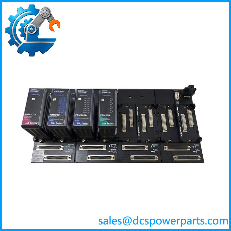
FBM217 I217TA24-OPTO
Application Scenarios & Field Pitfalls — The Engineer’s Perspective
Engineering Pain Point
The common field problem with an replacement is treating the termination assembly as a generic accessory. The family supports several electrical input arrangements, including 30 VDC logic inputs, 24 VDC contact sensing, 132 VAC/150 VDC configurations, and 240 VAC configurations. The termination assembly determines important aspects of field isolation and signal conditioning. Using the wrong TA can therefore produce an electrically incompatible installation even when the FBM module itself is the correct part number.
Typical Applications
- 24 VDC digital status monitoring from switches, contacts, relays, and discrete field devices.
- DCS equipment status acquisition for pumps, motors, valves, breakers, and auxiliary equipment.
- Process interlock inputs where discrete field states are brought into a Foxboro control strategy.
- Existing Foxboro I/A Series installations requiring replacement of an and its associated termination hardware.
Technical Pitfalls to Avoid
- Do not confuse with the termination panel. is the 32-channel input module; is the associated field termination assembly.
- Do not assume every uses . Published documentation lists multiple TA options for different field-signal arrangements.
- Verify the actual field voltage. A 24 VDC termination arrangement should not be substituted into a 120/132 VAC or higher-voltage input circuit.
- Check channel grouping and fuse allocation. The documentation available publicly identifies a 1 A fuse arrangement for 16 channels; verify the actual installed panel revision before applying this information to a safety-related circuit.
- Check the FBM-to-TA cable. The termination assembly is part of a defined FBM wiring architecture. A physically compatible connector does not prove that the cable pinout is correct.
- Preserve channel numbering. During replacement, compare field drawings against the TA terminal markings and FBM channel assignments rather than relying on the previous technician’s wire labels.
- Verify input logic after installation. For a 24 VDC discrete circuit, test both energized and de-energized states at the actual FBM input and confirm the DCS indication and configured logic.
Related Products
- — 32-channel discrete input interface module; the primary FBM electronics associated with this termination configuration.
- Foxboro RH916XZ — termination assembly for 32-channel 24 VDC contact sensing with contact wetting supplied by the FBM.
- Foxboro RH916CA — termination assembly for 30 VDC voltage-monitoring inputs.
- Foxboro RH916YA — termination assembly for 132 VAC / 150 VDC maximum voltage-monitoring applications.
- Foxboro RH916YB — termination assembly for higher-voltage contact-sensing applications using external excitation.
- Foxboro RH916PU — termination assembly for 240 VAC voltage-monitoring inputs.
These termination assemblies are not interchangeable simply because they connect to an . Their supported field-signal ranges and isolation arrangements differ.
Procurement Note
For a Foxboro replacement, purchase verification should cover both identifiers rather than only the FBM number:
+
Before installation, verify the FBM hardware revision, termination-panel revision, 24 VDC field architecture, FBM-to-TA cable, channel allocation, fuse arrangement, and existing Foxboro system configuration.
The strongest available documentation confirms ‘s 32-channel architecture and its multiple supported termination arrangements. The exact terminal-level specification is less completely documented publicly, so the installed nameplate and original Foxboro wiring documentation should take precedence over secondary catalog data.