Description
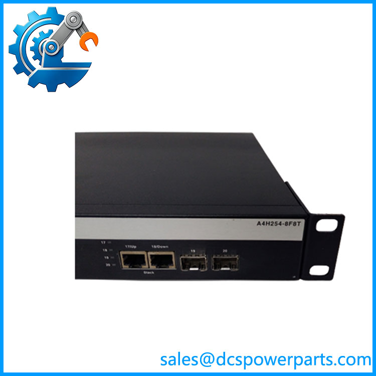
Foxboro A4H254-8F8T P0973JP | Managed Ethernet Switch | I/A Series Control Network
Key Technical Specifications
| Parameter | Specification |
|---|---|
| Manufacturer | Foxboro / Invensys |
| A4-Series Model | A4H254-8F8T |
| Foxboro Reference | P0973JP |
| Switch Type | Managed Ethernet switch |
| Copper Ethernet | 8 × 100Base-TX |
| Copper Connector | RJ-45 |
| Fiber Ethernet | 8 × 100Base-FX |
| Fiber Connector | MT-RJ |
| Fixed Gigabit Ports | 2 × 10/100/1000 Ethernet |
| SFP Uplinks | 2 × 1000Base-X |
| Duplex | Full duplex |
| Management | Local console, SNMP/RMON |
| VLAN | Supported |
| Port Mirroring | Supported |
| Mounting | Shelf, desk, or 19-inch rack |
| Redundant Power | Optional redundant power supply |
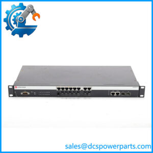
Foxboro’s control-network equipment documentation specifically identifies P0973JP as the 8-port copper / 8-port fiber A4-Series managed switch and describes the 20-port physical interface arrangement: eight 100Base-TX ports, eight 100Base-FX ports, two fixed 10/100/1000 ports, and two 1000Base-X SFP uplinks.
The same documentation lists VLAN capability, full-duplex operation, local-console configuration, SNMP/RMON monitoring, and port-mirroring diagnostics. An optional redundant power supply is available for installations requiring a second power path.
Product Introduction
The Foxboro A4H254-8F8T P0973JP is an A4-Series managed Ethernet switch intended for industrial control-network applications. Its combination of copper and multimode fiber interfaces allows control-network equipment using different physical media to share the same managed Layer 2 switching infrastructure.
For a legacy Foxboro I/A Series installation, this type of switch is more than a simple Ethernet hub. Port configuration, VLAN settings, fiber transceiver selection, uplink topology, and redundant-power arrangements can all affect restoration of the control network after a hardware replacement.
A4H254-8F8T P0973JP
Application Scenarios & Field Pitfalls — The Engineer’s Perspective
Engineering Pain Point
A failed control-network switch can make multiple controllers or workstations appear to fail at the same time. Before replacing control processors, check the network layer. With the A4H254-8F8T, the mixed copper/fiber architecture adds another diagnostic variable: a fault may be isolated to a copper port, MT-RJ fiber path, SFP uplink, configuration, or power path.
Typical Applications
- Foxboro I/A Series control-network infrastructure
- Industrial DCS Ethernet aggregation
- Copper-to-fiber control-network connections
- Control-room and equipment-room network aggregation
- Legacy process automation network maintenance
- Fiber-connected remote control equipment
Technical Pitfalls
- Do not confuse P0973JP with a generic unmanaged switch.
The OEM documentation identifies it as a managed A4-Series Ethernet switch with configuration and diagnostic functions. - Verify the fiber connector type.
The eight 100Base-FX ports use MT-RJ connectors. This is important when replacing older fiber infrastructure because connector and transceiver compatibility cannot be assumed from the phrase “100Base-FX” alone. - Do not assume every Gigabit port has the same function.
Two ports are fixed 10/100/1000 Ethernet interfaces, while two additional ports are 1000Base-X SFP uplinks. Their physical interfaces and intended deployment should be checked before moving cables during a shutdown. - Configuration backup matters.
A hardware replacement is not necessarily a plug-and-play network restoration. VLAN assignments, port settings, spanning-tree behavior, management configuration, and uplink arrangements should be documented before removing a functioning unit. - Redundant power requires plant wiring verification.
The OEM documentation notes that the optional redundant supply requires two separate branch circuits. Do not assume that installing the redundant supply alone creates power-path redundancy. - Fiber faults can look like switch faults.
Before condemning the switch, inspect the MT-RJ connection, fiber polarity, patching, optical transceivers, and remote endpoint. A clean link indication at the switch does not prove the complete fiber path is healthy. - Check the exact network architecture before substitution.
A modern industrial Ethernet switch may provide similar port counts but still differ in VLAN behavior, management functions, spanning-tree implementation, SFP compatibility, or configuration retention. Functional equivalence is not the same as field interchangeability.
Related Products
- Foxboro P0973JM / Enterasys A4H124-24TX — A4-Series managed copper Ethernet switch with a different port configuration.
- Foxboro P0973JN / Enterasys A4H124-24FX — A4-Series fiber Ethernet configuration; port media differs from P0973JP.
- P0973JX — Optional redundant power-supply assembly associated with the A4-Series switch family.
- A4H254-8F8T — The Enterasys A4-Series hardware designation corresponding to Foxboro P0973JP.
- Foxboro I/A Series control network equipment — Host network environment in which the may be deployed.
- 100Base-FX fiber infrastructure — Optical network segment requiring matching fiber type, connector, and transceiver configuration.
- 1000Base-X SFP modules — Pluggable uplink hardware used by the switch’s Gigabit SFP interfaces.
Procurement Note
For a critical Foxboro network spare, specify both identifiers: A4H254-8F8T and . The two identifiers establish the hardware and Foxboro system reference and reduce the chance of receiving a similar-looking A4-Series switch with a different port arrangement.
Before installation, record the existing port-to-device mapping, VLAN configuration, uplink arrangement, SFP type, fiber patching, management settings, and power configuration. For a used or refurbished unit, inspect every RJ-45 and MT-RJ interface, SFP cage, console connector, power connector, and front-panel indicator before putting it into a live control network.