Description
Product Overview
FBM233 is not an Ethernet card in the sense of something that moves packets for a controller. It is a Field Device System Integrator: a field-mounted module whose job is to make devices that were never designed to speak I/A Series appear, inside the control database, as ordinary DCI blocks that a control block can read and write.
The part number for this module is P0926GX, printed as such in the product specification sheet, and it identifies the redundant member of the pair — FBM232 is the simplex sibling. It carries one 10/100 Mbps copper Ethernet port on a single RJ-45 at the front, which sounds at odds with the word “redundant” until you see where the redundancy lives: not in a second port, but in a second module. Two FBM233 modules form a Master/Tracker pair, mounted in adjacent odd and even positions on the same Modular Baseplate, and either one can carry the device traffic.
The flexibility that makes this module worth its price is that it has no protocol of its own. It is generic Ethernet hardware, and the protocol arrives as a downloadable software driver plus an XML device configuration file, loaded from the engineering environment. Modbus TCP against a drive, EtherCAT-adjacent vendor protocols, a private UDP stream from an analyser — the difference is the driver image, not the card. Which also means the module’s useful life is tied to a driver library, not to a silicon revision.
Its position in the architecture is deliberate: a 2 Mbps Module Fieldbus connects it to an FCM100Et, FCM100E or FCP270, the module accepts either path of that redundant fieldbus, and up to 2000 DCI connections can be made from the control station. One pair of modules can therefore absorb 64 field devices — smart transmitters, valve positioners, analysers, drives, PLCs — into the same historian and the same alarm scheme as hardwired I/O, without a separate communication server and without touching the control strategy.
Technical Specifications
| Parameter | Value |
|---|---|
| Product model | FBM233 |
| Part number | P0926GX |
| Manufacturer | Foxboro (Schneider Electric) |
| Product type | Field Device System Integrator (FDSI), redundant |
| Field interface | 1 × RJ-45, 10/100 Mbps copper Ethernet |
| Protocol basis | UDP/IP or TCP/IP; IP address fixed or DHCP |
| Protocol implementation | Downloadable I/O software driver plus XML device configuration |
| Field device capacity | Up to 64 devices per module pair |
| DCI connections | Up to 2000 per control station |
| Fastest ECB block period | 500 ms |
| Module Fieldbus | Redundant 2 Mbps, via FCM100Et, FCM100E or FCP270 |
| Power supply | 24 VDC redundant, +5%/−10%, 7 W maximum |
| Heat dissipation | 7 W maximum per module |
| Operating temperature | −20 °C to +70 °C |
| Storage temperature | −40 °C to +70 °C, 5–95% RH non-condensing |
| Environmental class | ISA S71.04 Class G3 (harsh) |
| Dimensions | 102 mm × 45 mm × 104 mm (114 mm with mounting lugs) |
| Mass | 284 g |
| Mounting | Modular Baseplate, 4 or 8 slots, DIN rail or 19-inch rack |
| Cable length | 1 m to 100 m to hub, switch or device |
| Regulatory | UL/UL-C Class I Div 2 T4; ATEX EEx nA IIC T4 (Zone 2); EN 61326 Annex A, CISPR 11 Class A |
| Calibration | Not required |
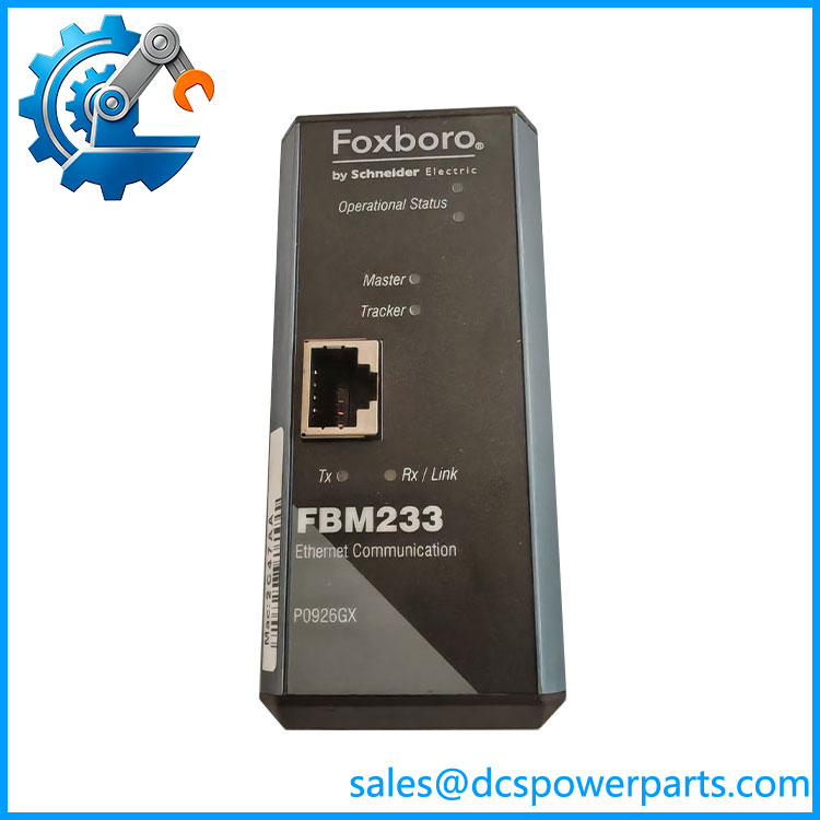
FBM233 P0926GX
Key Features and Advantages
A protocol library instead of a product line: the same FBM233 integrates a Modbus TCP drive, a device with a vendor-private UDP stream and a packed-digital PLC interface, because the driver is downloaded rather than built in. Plants that standardized on this module stopped buying a different gateway for every third-party device, and stopped carrying a different spare for every gateway.
Redundancy placed where it actually fails: copper Ethernet ports fail at the magnetics, and cables fail at the connector. Putting one port per module and pairing the modules means a failed port, a failed transceiver or a dead processor costs a switchover rather than a loss of all 64 devices. The Master/Tracker arrangement is automatic, and the pair draws its power from redundant 24 V feeds, so a single supply loss is also survivable.
Capacity per slot that legacy I/O cannot match: 2000 DCI connections from one pair, with packed digital values carrying up to 32 points per connection, is a theoretical 64,000 discrete values through two slots. On a plant where cabinet space is the binding constraint and the cabinet is already twenty years old, this is the argument that wins.
A defined engineering boundary: the fastest ECB block period is 500 ms, and that number is honest about the module’s role. It is a supervisory data path — device diagnostics, analyser results, drive status, remote PLC tags — not a substitute for hardwired I/O on a trip path or an interlock. Knowing this before the design review prevents the retrofit that later has to be re-engineered.
Field-mounted and harsh-area rated: Class G3 contamination tolerance, −20 to +70 °C, and UL Class I Div 2 / ATEX Zone 2 certification mean the module can sit in the field cabinet next to the devices rather than in the marshalling room, which removes the long copper runs that a centralized gateway would need.
Configurable redundancy behaviour, which is also a liability: the Master/Tracker pair can be set to switch automatically or to stay put until an engineer commands it. The second setting is chosen to prevent nuisance transfers, and it is exactly the setting that leaves a plant running on a degraded master with no switchover. It belongs in the maintenance record, not only in someone’s memory.
Applications
Refineries and petrochemical units: bringing packaged unit PLCs, third-party analyser shelters and skid controllers into the same I/A Series database as the process I/O, so that a shift operator sees the sulphur unit’s vendor skid on the same faceplate scheme as the rest of the plant.
Power generation auxiliary systems: water treatment, ash handling and fuel handling PLCs whose data has to appear on the DCS overview without building a second SCADA system — the classic case for a pair of FBM233 modules and a small Ethernet switch.
Offshore and hazardous process areas: field cabinets in Class I Div 2 or Zone 2 locations where the module’s own certification removes the need for a separate purge or explosion-proof enclosure around a commercial gateway.
Pharmaceutical and food batch plants: intelligent weighing terminals, valve islands and vision systems integrated over Ethernet so that batch records draw device-level data directly, with the module’s driver library providing the audit-relevant protocol translation.
Legacy DCS life extension: installations where the control strategy must not change but the plant now needs equipment diagnostics and historian coverage from smart field devices — the least invasive route is a pair of communication modules in existing baseplate slots.
Water and wastewater networks: lift stations and dosing skids connected over Ethernet into a central Foxboro system, with the 500 ms scan floor comfortably adequate for reservoir and flow data.
Related Products
FBM232 — simplex FDSI sibling on the same 10/100 Mbps Ethernet basis; single module, no Master/Tracker pair. FCM100Et — Fieldbus Communication Module that interfaces the redundant 2 Mbps Module Fieldbus used by FBM233. FCM100E — earlier Fieldbus Communication Module performing the same baseplate interface role. FCP270 — Field Control Processor, an alternative host for the module Fieldbus; FCP280 in later I/A and Evo configurations. FBM223 — PROFIBUS DP interface module in the same family, for fieldbus devices rather than Ethernet devices. FBM243 — PROFIBUS DP master interface module, a different integration route for the same cabinet. P0971PK — null hub adapter used where the Ethernet topology requires it. P0972WE — 10 Mbps hub documented alongside the module for legacy field networks. FPS400-24 — 24 VDC power supply used with the hub and module arrangement. Modular Baseplate (4-slot / 8-slot) — the carrier that provides slot positions, power feeds and the 2 Mbps fieldbus connection.
Installation and Maintenance
Before installation: confirm the baseplate positions. Redundant modules must occupy an odd slot and the adjacent even slot — 1 and 2, 3 and 4, 5 and 6, or 7 and 8 — because the pairing is a property of the carrier, not of the module. Verify the 24 VDC feeds are genuinely independent, confirm the module Fieldbus reaches a live FCM100Et or FCP270 on both paths, and plan the Ethernet side as a switch or hub topology with cable runs inside the 1 m to 100 m window. Load the correct driver and XML device file from the engineering environment before the module is expected to produce data, and record the firmware and driver versions alongside the module’s serial number.
Maintenance practice: the module needs no calibration, so maintenance effort belongs on the two things that do drift — the network and the pair. Inspect RJ-45 connectors and cable strain relief at each outage, since a port that has been tugged is a port that will fail; confirm that the Master/Tracker pair is actually switching when commanded, and not held in manual; and compare the two modules’ data for the same device, because a tracker that is running but reporting slightly different register values produces trends that step whenever the control station happens to poll the other side. Keep the driver image and device configuration file archived with the system backup — a replacement P0926GX restored with the wrong driver version is a healthy module that cannot talk.
Warranty and Quality
Every FBM233 P0926GX is supplied with the module name and part number confirmed together, since both appear in the specification sheet and either alone can be misread as a different member of the baseplate family. Units are inspected for connector condition, label consistency and evidence of network-side damage before dispatch, and carry a 12-month repair, replacement or refund commitment. Technical support covers the questions this module actually raises in service: matching driver and firmware to the device being integrated, verifying the Master/Tracker pairing and baseplate slot rule, and confirming that the module’s capacity and 500 ms scan floor suit the application before it is installed rather than after.