Description
Key Technical Specifications
| Parameter | Specification |
|---|---|
| Product Model | A6500-RC |
| Manufacturer | Emerson |
| Product Series | AMS 6500 ATG |
| Product Type | System Relay Card |
| Digital Inputs | 66 |
| Input Isolation | Galvanically isolated |
| Logic Low | 0–3V |
| Logic High | 13–32V |
| Digital Input Current | 1mA |
| Logic Networks | 16 |
| Relay Outputs | 16 |
| Relay Contact Type | SPDT |
| Maximum Contact Voltage | 32VDC / 48VAC |
| AC1 Contact Rating | 48V / 2A |
| DC1 Contact Rating | 32V / 2A |
| DC-13 Contact Rating | 24V / 1A |
| AC-15 Contact Rating | 24V / 2A |
| NO Contact Switching Time | 10ms, excluding logic processing |
| NC Contact Switching Time | 13ms, excluding logic processing |
| Operating Temperature | -20 to +70°C |
| Storage Temperature | -40 to +85°C |
| Relative Humidity | 5–95%, non-condensing |
| Dimensions | 3U height, 10HP width; double Eurocard |
| Installation | A6500-xR system rack |
Specifications are based on Emerson’s October 2023 product sheet and December 2024 operating manual.
Product Introduction
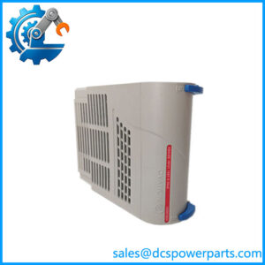
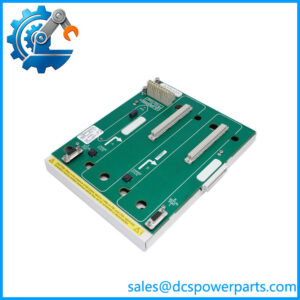
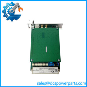
The Emerson A6500-RC is a programmable relay output card within the AMS 6500 ATG machinery protection system. Its main purpose is to convert monitoring-system status information into configurable relay actions. Signals such as Channel Clear, Alert, and Danger from installed measurement cards can be routed into the A6500-RC through the rack backplane. The card then applies Boolean logic and configurable time delays before activating the selected relay outputs.
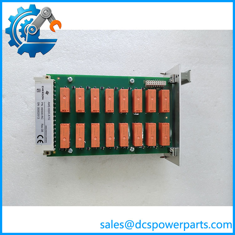
A6500-RC
The module provides 66 isolated digital inputs and 16 SPDT relay outputs. This arrangement allows machinery monitoring conditions to be mapped to external alarm, shutdown, annunciation, or control circuits. The A6500-RC is designed for installation in compatible AMS 6500 ATG racks and is not a standalone general-purpose PLC relay module.
Major Features and Advantages
16 independent relay outputs
The card provides 16 mechanical SPDT relay channels. Each output can be configured according to the required machinery monitoring or protection logic. Contact ratings must be respected when connecting external alarm and control circuits.
66 galvanically isolated digital inputs
The module accepts 66 digital inputs using 24V logic levels. The documented low-level range is 0–3V, while the active high-level range is 13–32V. Open inputs are interpreted as inactive.
Programmable Boolean logic
The A6500-RC supports configurable logic networks that combine monitoring signals. Engineers can select input conditions, apply logic functions, configure delays, and assign the resulting condition to an output relay.
Adjustable time delays
The product documentation describes configurable delays from 0 to 1,000 seconds. This allows alarm and relay behavior to be adapted to specific machinery protection requirements.
Compact rack installation
The 3U, two-slot plug-in design reduces cabinet space requirements compared with traditional 6U relay-card arrangements. The 10HP front-panel width is designed for the A6500-xR rack family.
Hot-swappable design
Emerson identifies the A6500-RC as a hot-swappable module. However, maintenance personnel must follow the applicable rack operating procedure and verify the plant’s protection architecture before removing or inserting the card.
Application Scenarios and Field Pitfalls
Typical applications include:
- Steam turbine overspeed and machinery alarm systems.
- Gas turbine vibration monitoring and shutdown interfaces.
- Compressor bearing protection.
- Hydro turbine monitoring and relay output control.
- Industrial machinery alarm and trip signal distribution.
Important engineering checks:
- Confirm the installed rack model: A6500-SR, A6500-RR, or A6500-FR.
- Record the existing relay logic configuration before replacement.
- Verify all 66 digital input assignments.
- Check SPDT contact wiring and NO/NC configuration.
- Confirm external circuit voltage and current against the relay contact ratings.
- Verify alarm and danger signal routing from the measurement cards.
- Test relay operation and external trip-circuit response after installation.
Field warning: The is a programmable relay card, not a substitute for the complete machinery measurement or protection system. Incorrect logic configuration or contact wiring can affect alarm and shutdown actions. Verify the complete protection sequence before returning equipment to service.
Related Products and Variants
| Model | Product Function |
|---|---|
| A6500-UM | Universal measurement card for speed, vibration, and position |
| A6500-TP | Temperature and process card |
| A6500-CC | System communication card |
| A6500-SR | Standard system rack |
| A6500-RR | Redundant relay rack |
| A6500-FR | Front termination rack |
| A6500-PE | Prediction Extension license |
These products belong to the AMS 6500 ATG system but have different hardware and functional roles.
Procurement and Quality Control
For an Emerson replacement, request:
- Front and rear photographs of the module.
- Complete model and serial-number identification.
- PCB revision and hardware condition.
- Digital input status test results.
- All 16 relay output functional test results.
- NO/NC contact continuity measurements.
- Verification of relay switching delays.
- Confirmation of compatibility with the installed AMS 6500 ATG rack.
- Clear declaration of new, used, repaired, or refurbished condition.
Engineering recommendation: The ‘s relay logic configuration is as important as its hardware condition. Before replacing an existing card, preserve the original logic assignments, delay settings, and output mapping. Test the actual external alarm and trip circuits rather than relying only on front-panel LED indications.