Description
Product Overview
G-TUB30/480ERSS0 is the 30-ampere member of Elmo’s Gold Tuba series: an AC servo drive that rectifies three-phase mains directly, up to 3 × 528 V ac, and delivers 18.5 kW of continuous output from a package the size of a hardback book. It is the drive you reach for when a machine has a 400 or 480 V bus, a large permanent-magnet motor, and no room for a drive cabinet with a transformer in front of it.
The direct-to-mains capability is not a marketing simplification — it rests on a specific piece of construction. The power stage of the Gold Tuba is fully isolated from the control stage and from the heat sink, so the drive can be connected to a non-isolated supply with the neutral at the midpoint of the rectified DC bus, and the control common can be tied to protective earth for EMI performance. Elmo states the consequence plainly: the isolation transformer that a conventional 480 V drive needs becomes optional. On a multi-axis machine that is a cabinet-height and cost decision, not a footnote.
The current specification is the one that catches people out. Elmo rates the Gold Tuba in DC amperes — the figure you use for trapezoidal commutation or a DC brush motor — and states that the sinusoidal RMS rating is that DC value divided by 1.41. For this model that means 30 A dc amplitude continuous, but only 21 A RMS continuous for a sinusoidally commutated brushless motor, with 60 A peak available for acceleration. A motor selected against 30 A RMS will be overloaded by roughly forty percent on a sinusoidal drive, and the failure shows up as thermal trips at the machine’s heaviest axis rather than as an obvious fault.
Also easy to miss: the drive does not run without its auxiliary supply. G-TUB30/480ERSS0 needs an isolated 24 V dc ±10 % source rated 20 VA for the 30 A models, and it needs it whether or not parameter backup is wanted — the auxiliary rail powers the control electronics, and the backup function is a by-product, not an option that lets you skip the supply.
The last thing to settle before ordering is what the tail string means. Elmo’s guide assigns the communication build by a letter in the product number: the EtherCAT build with switches is identified by an F, a plain EtherCAT build by an E, and a CAN build by an S in the corresponding position. Those same letters also appear in the digital I/O position, where S denotes the PLC-source I/O variant, T the TTL variant and H the high-level input variant. So the string must be read position by position rather than by scanning for a familiar letter. This article describes the 30 A / 480 V platform and the option set that the string selects from; the surest confirmation of protocol and I/O build for a specific unit is the part-number sticker on its side, which Elmo’s guide explicitly tells installers to check against the ordered type.
Technical Specifications
| Parameter | Value |
|---|---|
| Model | G-TUB30/480ERSS0 (equivalent listing form G-TUB30480ERSS0) |
| Manufacturer | Elmo Motion Control Ltd., Israel |
| Series | Gold Line — Gold Tuba (G-TUB) |
| Product type | Single-axis AC servo drive, direct-to-mains, panel/wall mount |
| Nominal supply | 3 × 400 V ac / 3 × 480 V ac, dc to 500 Hz |
| Supply range | 3 × 140 V ac minimum; 3 × 528 V ac maximum |
| Continuous power output | 18.5 kW at 480 V |
| Continuous current | 30 A dc amplitude (trapezoidal or DC motor); 21 A RMS for sinusoidal commutation |
| Peak current | 60 A |
| Built-in shunt regulator | 5.9 kW peak, switching type, with duty-cycle limiter that inhibits the shunt above 2 % on/off ratio |
| Efficiency | Greater than 98 % at rated power at nominal conditions |
| Auxiliary supply | 24 V dc ±10 %, isolated source, 20 VA for 30 A models; required for operation |
| Feedback | Ports A, B and C — incremental encoder, digital Hall, absolute serial (EnDat, BiSS, SSI, Tamagawa, Panasonic, Sanyo Denki), resolver, interpolated analog/SinCos, HIPERFACE; single, dual and gantry loop configurations |
| Port C | 15-pin high-density D-type: emulated encoder differential output plus one differential ±10 V analog input |
| Digital I/O | 6 inputs and 4 outputs on a 15-pin high-density D-type; TTL, PLC-source or PLC-sink type according to the part number |
| Network I/O option | 12 extended inputs, 6 extended outputs and a second differential ±10 V analog input on a 26-pin high-density D-type; fitted only to the extended-I/O build |
| Communication | EtherCAT (two RJ-45, IN/OUT) or CANopen according to the tail letter; USB 2.0 host port for EAS II |
| Safety | STO with two inputs and return, SIL 3 to IEC 61800-5-2:2007, PL e Cat 3 to EN ISO 13849-1:2008 |
| Standards | IEC/EN 61800-5-1, UL 61800-5-1, UL 508C, UL 840, CSA C22.2 No. 14-13, CE 2006/95/EC |
| Physical | 241 × 86.1 × 180.1 mm, 3.25 kg, vertical wall mount with M6 screws through the heat sink |
| Recommended upstream protection | 40 A Type C circuit breaker, 40 A contactor; 14 AWG for AC input and PE on the 30 A model |
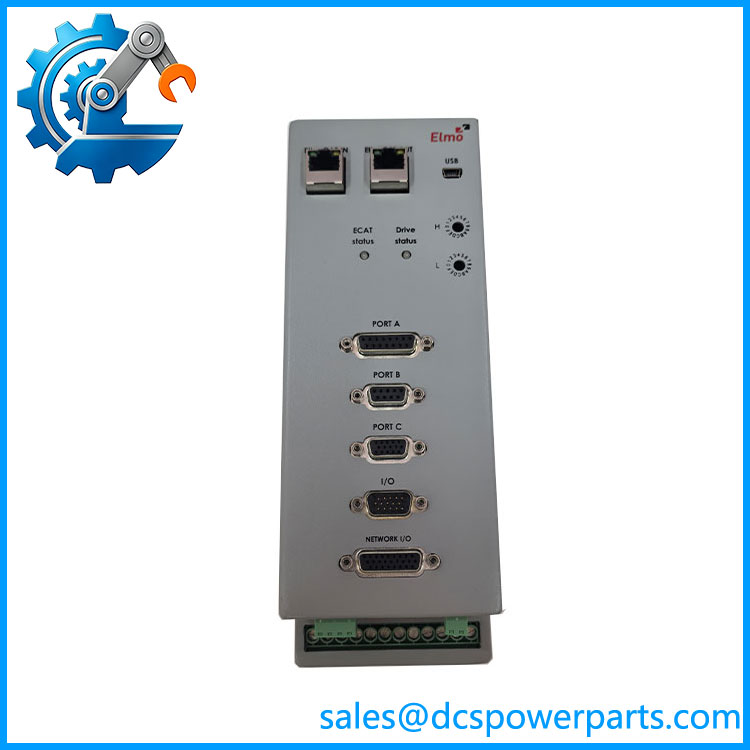
G-TUB30480ERSS0
Key Features and Advantages
No isolation transformer in the feed: the power stage is isolated from the control stage and heat sink, so the drive accepts a direct, non-isolated mains connection and the cabinet loses a component that normally costs more than the drive.
Regeneration handled inside the box: a 5.9 kW switching shunt holds the DC bus during deceleration, and the duty-cycle limiter disables it once the on/off ratio passes 2 %, which protects the shunt on high-inertia loads instead of quietly cooking it.
DC-link sharing across axes: the VP+ and VN- terminals let one unit feed several drives, so a multi-axis machine shares a DC bus and its braking energy instead of buying a supply per axis and dissipating every stop in resistors.
Speed and position bandwidth from a compact frame: the Gold Line core control runs current, velocity, position and advanced position modes with vector control, which is what allows a drive this small to hold a demanding axis without an external controller.
Feedback flexibility on three ports: incremental, absolute serial, resolver and SinCos encoders are all accepted, and dual and gantry loop configurations are supported — a machine can mix encoder types across axes without a different drive per feedback type.
STO as a certified function, not a suggestion: two STO inputs with a return, rated SIL 3 and PL e Cat 3, remove torque without dropping the main contactor, so a safety stop does not mean a power-down and a re-homing cycle.
Extended I/O for local logic: the network I/O build adds twelve inputs, six outputs and a second analog input on the drive itself, which is enough for a clamp, a brake release and a pressure transducer without a remote rack.
Commissioning without guesswork: phase order is arbitrary because EAS II establishes commutation during setup, so a motor that turns the wrong way is a software correction rather than a rewiring job.
Applications
Machine tools and machining centres: 480 V spindle and axis drives fed straight from the machine’s three-phase supply, where cabinet depth is the constraint and a transformer-fed drive will not fit.
High-power packaging and converting lines: unwind, rewind and main-drive axes on film, foil and board machines, where regeneration during deceleration is continuous and the internal shunt plus DC-link sharing carry it.
Plastics and rubber machinery: extruder and roll drives at 400/480 V that need high continuous torque in a small frame, with STO used for guard-door stops on the line.
Metals processing: coil handling, tension and traverse axes on strip lines, where multiple drives share a DC bus and braking energy from one axis is available to another.
Test stands and dynamometers: 480 V load and drive motors on the same DC link, with the shunt absorbing the difference during rapid direction changes.
Print and paper finishing: web tension and registration axes where an absolute serial encoder per roll is normal and the drive’s three feedback ports avoid a separate interface module per axis.
Crane, hoist and lifting axes: brake control and STO on the drive, with the 5.9 kW shunt handling the energy a descending load returns.
Related Products
G-TUB40/480 — the 40 A / 480 V member of the same family, 25 kW continuous with 35 VA auxiliary power and an 11 kW shunt; the next step up when 30 A RMS is not enough. G-TUB45/480 — the newest 480 V build at 45 A / 32 A RMS / 90 A peak and 28 kW, now the highest-power member of the line. G-TUB30/230 — the 230 V sibling, 9.5 kW, with 1 × 230 V or 3 × 230 V input and a 270 V ac maximum; the single-phase-capable model for smaller machines. G-TUB30/480FEHSNA2 — a 480 V EtherCAT build selected by the F tail letter, being the EtherCAT version with switches and a different digital I/O type. G-BAS10/230 — a smaller Gold Line drive for axes that need the Gold control core but not the Gold Tuba’s power stage. G-TUBA056A — the 15-pin high-density D-type connector specified for Port C feedback output and analog input. G-TUBA031A — the USB connector part used on the drive’s programming port. Gold Tuba Cable Kit — Elmo’s documented cable set for the power, feedback and STO connectors, the shortest route to a correctly shielded harness. EAS II (Elmo Application Studio) — the Windows commissioning tool that establishes commutation, tunes the loops and configures the drive; supplied as part of the product set.
Installation and Maintenance
Before installation: confirm the tail string against the ordered type using the part-number sticker, because G-TUB30/480ERSS0 is one selection from a family whose communication and I/O builds are distinguished by letters that also appear elsewhere in the string; wiring an EtherCAT master to a CAN build, or a TTL I/O harness to a PLC-source build, is the predictable result of reading the string by glance. Verify the motor’s continuous rating against 21 A RMS rather than 30 A, and confirm the load can accept 60 A peaks. Check that a 24 V dc isolated auxiliary supply of at least 20 VA is available — the drive will not operate without it — and that the upstream protection is a 40 A Type C breaker with a 40 A contactor.
Installation: mount the drive vertically with the heat sink against the machine chassis, using M6 screws through the openings, and keep the AC feed on 14 AWG conductors including protective earth. Use a four-wire shielded (not twisted) cable for the motor and a shielded twisted-pair cable for the 24 V feed, with the shield tied to the nearest protective earth at the supply end. Where the drive is connected directly to mains, the supply must not exceed 528 V ac, and the neutral point must be understood as the midpoint of the rectified bus rather than the most negative node. Where a DC link is shared between axes, connect VP+ and VN- only to drives that are themselves isolated-DC types.
Maintenance: monitor the DC bus and shunt behaviour on axes with high inertia — repeated shunt inhibition is a sign the deceleration profile is returning more energy than the resistor can absorb, and the answer is a shorter ramp or a shared DC link, not a bigger shunt. Keep the fan and heat-sink fins clear, since the whole thermal design assumes chassis conduction and vertical airflow. On an STO-equipped machine, remember that configuring the STO status output removes OUT4 and IN6 from the local I/O, which surprises maintenance teams who assumed four outputs were always available. When replacing a drive, carry the EAS II project across: the commutation setup, feedback configuration and I/O assignment live in software, and a replacement unit out of the box is an unconfigured drive.
Warranty and Quality
Every G-/480ERSS0 is supplied as the Elmo Gold Tuba 30 A / 480 V servo drive defined by Elmo’s Gold Tuba installation guide and product data, not as the generic high-power drive or the mislabelled platform that resale pages describe. Documented for this model: 3 × 400/480 V ac nominal supply with a 3 × 140 V ac minimum and 3 × 528 V ac maximum from dc to 500 Hz; 18.5 kW continuous output; 30 A dc-amplitude continuous current equivalent to 21 A RMS sinusoidal, with 60 A peak; a 5.9 kW switching shunt with a 2 % duty-cycle limiter; efficiency above 98 % at rated power; an isolated 24 V dc ±10 % auxiliary supply at 20 VA that the drive requires to operate; feedback on Ports A, B and C covering incremental, digital Hall, absolute serial, resolver and SinCos encoders, with Port C also providing an emulated encoder output and a differential ±10 V input; 6 digital inputs and 4 digital outputs in TTL, PLC-source or PLC-sink form according to the part number; an optional extended network I/O set of 12 inputs, 6 outputs and a second analog input; EtherCAT or CANopen by tail letter plus a USB 2.0 programming port; STO rated SIL 3 to IEC 61800-5-2:2007 and PL e Cat 3 to EN ISO 13849-1:2008; conformity to IEC/EN 61800-5-1, UL 61800-5-1, UL 508C, UL 840, CSA C22.2 No. 14-13 and CE 2006/95/EC; and 241 × 86.1 × 180.1 mm at 3.25 kg in a vertical wall mount. Units are inspected for heat-sink and fan condition, connector and D-type shell integrity, signs of DC-bus damage or shunt discolouration, and for the part-number sticker against the ordered type. Four corrections are stated plainly: this is Elmo’s Gold Tuba and not an ABB module, and numbers of the 1080-013xx form do not belong to it; the 30 A figure is dc amplitude while sinusoidal continuous current is 21 A RMS, so the drive must not be selected on the larger number; it is not usable without an external isolated 24 V dc supply; and its communication protocol and digital I/O type are fixed by the tail characters of the part number, with E, F and S also carrying I/O meanings in other positions, so protocol must be confirmed from the unit’s sticker rather than inferred from the model string. Auxiliary current draw beyond the 20 VA figure, per-axis thermal derating and ambient limits are not quoted here because they are outside the data verified for this model. A 12-month repair, replacement or refund commitment applies from installation, consistent with Elmo’s warranty term. Technical support covers reading the tail string before an order is placed, selecting a motor against RMS rather than DC current, the 24 V auxiliary and direct-to-mains connection requirements, shunt and DC-link behaviour on regenerative axes, and STO wiring including the loss of OUT4 and IN6 when the status output is configured.