Description
Product Introduction
When a controller cannot read position or encoder feedback, a failed interface board can interrupt machine operation and make fault isolation difficult. The BK684SSI470 is listed in industrial spare-part sources as an SSI interface board, suggesting a role in transferring synchronous serial interface signals within a compatible control system.
For replacement planning, verify the installed board’s manufacturer, connector layout, encoder interface, and controller compatibility before ordering. Public technical information for this exact part is limited, so detailed electrical specifications should be taken from the original documentation or confirmed against the physical unit rather than assumed from the model number.
Key Technical Specifications
| Parameter | Details |
|---|---|
| Model number | BK684SSI470 |
| Alternate listing | BK684SSI470-SSI |
| Associated brand reference | MASIC; manufacturer identity not independently verified |
| Product type | SSI interface board, based on supplier descriptions |
| Application | Industrial control-system interface; exact application unconfirmed |
| SSI channel count | Not verified |
| Encoder compatibility | Not verified |
| Signal voltage and electrical levels | Not verified |
| Communication format and data rate | Not verified |
| Connector and pinout | Must be checked against the original board |
| Compatible controller | Not confirmed |
| Operating temperature | Not verified |
| Installation method | Verify mounting and backplane arrangement on the installed system |
| Condition and warranty | Supplier-specific; obtain written confirmation |
Procurement note: Do not publish a specific voltage, channel count, baud rate, or controller compatibility claim until a matching datasheet, schematic, or original nameplate is available.
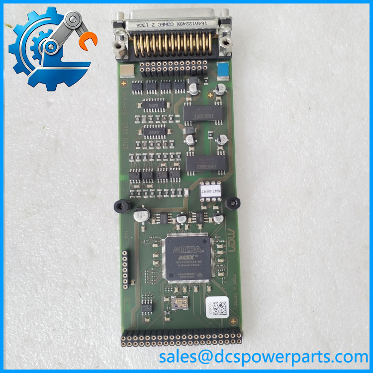
BK684SSI470
Application Scenarios & Pain Points
An interface fault can appear to be an encoder, wiring, or controller problem. Correct identification is essential before replacing the board.
- SSI signal interfacing: Potential use in equipment that relies on SSI-based position or encoder feedback; the precise supported signal format must be confirmed.
- Industrial equipment maintenance: Candidate spare for a failed board when the installed part number and connector arrangement match.
- Legacy control-system support: May be relevant when maintaining older equipment for which original hardware is difficult to source.
- Fault isolation: Compare the encoder, cable, supply, and controller diagnostics before concluding that the interface board has failed.
These are application areas suggested by the SSI interface designation, not independently verified functions of every BK684SSI470 variant.
Related Products
The following models appear in listings alongside BK684SSI470 or are described as related BK-series hardware. Confirm their exact roles and compatibility before treating them as substitutes.
- BK684AM351 — Related BK-series control hardware; exact function and compatibility require verification.
- BK698CPA15B0 — Listed as a BK-series CPU/control board; not an SSI interface replacement.
- BK684HSC720 — Associated with high-speed counter functionality in a related BK hardware listing; confirm the original catalog.
- BK684PBM570 — Associated with PROFIBUS-related communication hardware; a different interface function.
- BK684DOM280 — Associated with digital-output functionality in a related BK hardware listing; not equivalent to an SSI board.
Engineer’s Guide: Before You Order
1. Confirm the board identity. Warning: Match the complete BK684SSI470 designation, any -SSI suffix, and every additional part or revision number on the physical label.
2. Verify the SSI electrical interface. Confirm encoder supply, signal levels, clock and data connections, connector pinout, and supported data format. SSI should not be confused with other encoder interfaces simply because they serve similar applications.
3. Check system-level compatibility. Compare the backplane, board dimensions, firmware or controller requirements, and wiring diagrams. A matching product-family prefix does not establish that two boards can be exchanged.
For used or refurbished stock, request clear front-and-back photographs, connector close-ups, a functional test report, warranty terms, and confirmation that the board has not been modified.
Frequently Asked Questions
Q1. What is the used for?
Supplier listings describe it as an SSI interface board. The exact controller and machine application have not been verified from authoritative manufacturer documentation.
Q2. Is the same as -SSI?
The two designations appear together in a supplier listing, but an official manufacturer cross-reference was not found. Check the actual nameplate and any revision or secondary part number before ordering.
Q3. Which brand manufactures ?
A listing associates the model with MASIC, but that does not conclusively establish the original manufacturer. Confirm the logo, label, and equipment documentation before assigning a definitive brand.
Q4. Which encoder types can this board support?
The SSI designation suggests a synchronous serial interface, but the supported encoder resolution, data length, clock frequency, and electrical levels remain unverified. Obtain the original datasheet or machine wiring documentation.
Q5. Can I replace it with another BK-series board?
Not based on the BK prefix alone. CPU boards, communication boards, counter modules, and output boards have different functions. A replacement must match the required interface and hardware configuration.
Q6. How do I verify a refurbished ?
Request photographs of the actual unit, label and revision details, connector condition, test results, and written warranty coverage. If possible, compare the unit with a known-good board or original engineering drawing.
Q7. What information should I provide to identify the exact replacement?
The most useful evidence is a clear photograph of the complete board label, the front and rear of the PCB, connector markings, and the machine or controller model in which it is installed. Those details can help distinguish the correct variant from similarly named legacy parts.