Description
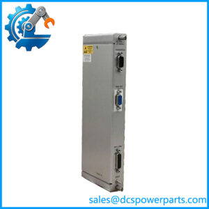
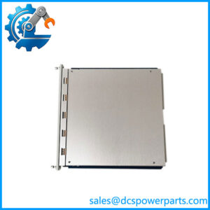
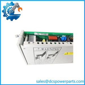
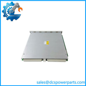
Bently Nevada 3500/34 | TMR Relay Module | 3500 Machinery Protection System
Key Technical Specifications
| Parameter | Specification |
|---|---|
| Manufacturer | Bently Nevada |
| Model | 3500/34 |
| Product Type | TMR Relay Module |
| Relay Channels | 4 |
| Architecture | Triple Modular Redundancy |
| Voting Logic | 2-out-of-3 |
| Relay Paths | 3 independent paths per channel |
| Total Relay Elements | 12 |
| Power Consumption | Approximately 9.6 W typical |
| Operating Temperature | -30°C to +65°C |
| Storage Temperature | -40°C to +85°C |
| Humidity | Up to 95%, non-condensing |
| Front Module Size | Approx. 120.4 × 24.6 × 241.8 mm |
| Front Module Weight | Approx. 0.34 kg |
The Bently Nevada documentation describes the 3500/34 TMR Relay Module as two half-height monitor modules plus a full-size TMR relay I/O module. The I/O section contains triplicate relay logic, with each channel using three independent relay signals to implement 2-out-of-3 voting.
Product Introduction
The Bently Nevada 3500/34 is the TMR relay module for the 3500 Machinery Protection System. Its purpose is to take alarm information from a configured TMR monitor group and provide trip or alarm contacts through three independent relay paths. The voting arrangement allows the system to make a relay decision using 2-out-of-3 logic, which is particularly important where an individual monitor or signal path should not cause an unwanted machinery trip.
Unlike the 3500/32 4-Channel Relay Module, the 3500/34 is specifically intended for a TMR rack architecture. The relay hardware therefore needs to be considered together with the TMR monitors, TMR Rack Interface Module, rack configuration, and external trip circuit.
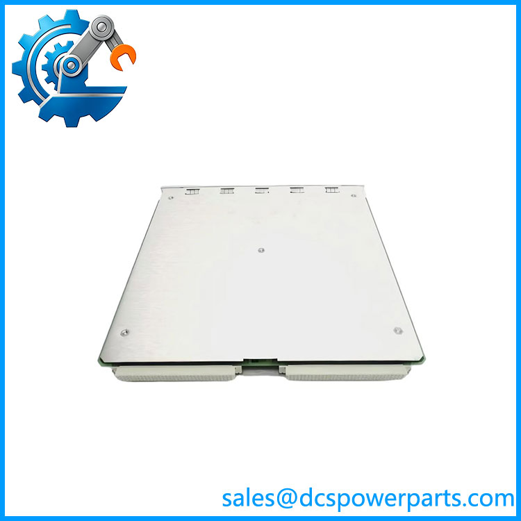
350054-03-00
Application Scenarios & Field Pitfalls — The Engineer’s Perspective
Engineering Pain Point
A relay module in a machinery protection system is part of the actual shutdown path. A simple continuity test on the relay contacts does not prove that the complete TMR voting arrangement is operating correctly. With the 3500/34, the monitor configuration, inter-module communication, relay logic, and external trip wiring all need to agree.
Typical Applications
- Steam and gas turbine protection
- Compressor machinery protection
- Generator and rotating-equipment shutdown systems
- Critical alarm and interlock circuits
- 3500 TMR machinery protection installations
Technical Pitfalls
- Do not confuse 3500/34 with 3500/32. The 3500/32 is the standard four-channel relay module, while 3500/34 is the TMR relay module. Their system architectures are different.
- TMR requires the complete architecture. The 3500/34 works with three monitor paths and a TMR Rack Interface Module. Installing the relay module into a non-TMR configuration does not create a TMR protection system.
- Verify the 2oo3 logic. Each relay channel receives three independent alarm contact signals. The TMR relay I/O section performs the voting rather than simply paralleling three relay contacts.
- Save the configuration before replacement. The maintenance documentation recommends saving the module configuration through the 3500 Rack Configuration Software before replacing the module, then downloading the configuration to the spare and verifying operation.
- Check the complete trip circuit. External interposing relays, shutdown solenoids, annunciators, wiring, and contact suppression can all affect the final trip response. A replacement relay module should not be accepted solely because its front-panel LEDs appear normal.
- Part number matters. The 3500/34 is a product family designation; the exact ordering number and option code should be matched to the installed rack and required relay/contact configuration before procurement.
Related Products
- 3500/32 — Standard 4-channel relay module; single relay path per channel rather than the TMR architecture of the 3500/34.
- 3500/32M — Updated 4-channel relay module family used in later 3500 configurations.
- 3500/04 — 3500 rack/interface hardware; exact rack option should be verified for the installed system.
- 3500/05 — Portable rack-related hardware used in 3500 system configurations.
- 3500/22M — Transient Data Interface, providing communication between the 3500 rack and host systems.
- 3500/23 — Enhanced transient data interface family.
- 3500/40M — Proximitor/Seismic Monitor family for vibration and position measurements.
- 3500/42M — Proximitor/Seismic Monitor used for machinery vibration and position protection.
- 3500/50 — Tachometer module family for speed and rotational measurements.
- 3500/53 — Overspeed Detection System module for dedicated overspeed protection applications.
Procurement Note
For a 3500/34 replacement, verify the complete part number, rack architecture, TMR monitor configuration, relay contact arrangement, and external shutdown circuit. The most important distinction is architectural: 3500/34 is a TMR relay module with 2oo3 voting, not simply a higher-density version of the 3500/32.
For a running turbine or compressor protection system, I would also preserve the existing rack configuration before swapping the module and perform a controlled relay-function test after installation.