Description
Bender IRDH275B-435 Insulation Monitoring Device
Product Overview
The Bender IRDH275B-435 is an ISOMETER insulation monitoring device designed for continuously monitoring insulation resistance in unearthed AC, AC/DC, and DC IT systems. The -435 version monitors 3(N)AC systems from 0 to 793 V and DC systems from 0 to 650 V, while using a separate high-voltage auxiliary supply of 88–264 VAC or 77–286 VDC. This separation allows the device to monitor an electrical system without relying on that system as its operating supply.
The IRDH275B-435 uses Bender’s AMPPlus measurement method, which automatically adapts to the existing system leakage capacitance. That characteristic is important in modern installations containing rectifiers, converters, thyristor-controlled DC drives, switching power supplies, and other equipment that can introduce substantial capacitive coupling to earth. Two independently adjustable response values from 1 kΩ to 10 MΩ allow separate prewarning and alarm thresholds.
The “B” version adds several functions that are absent from the basic IRDH275: a galvanically isolated RS-485 BMS interface, history memory with real-time clock for alarm events, and an electrically isolated 0(4)–20 mA output corresponding to the measured insulation value. Bender identifies B91065101 as the ordering number for the IRDH275B-435.
Product Introduction
Ground-fault detection in an unearthed IT system is not simply a matter of measuring line voltage. The IRDH275B-435 continuously evaluates insulation resistance between the monitored conductors and earth, then provides configurable alarm information when resistance falls below the selected thresholds. Bender specifically designed the series for AC, DC, and mixed AC/DC systems with power electronics and elevated leakage capacitance.
For a legacy electrical-system replacement, the complete suffix matters. IRDH275-435, IRDH275B-435, and IRDH275BW-435 share the same basic monitored-voltage and supply class, but the B version adds BMS communication and event-memory functions, while the W designation relates to enhanced mechanical/environmental resistance.
Key Technical Specifications
| Parameter | Value |
|---|---|
| Product Model | |
| Manufacturer | Bender |
| Product Family | ISOMETER IRDH275(B) |
| Product Type | Insulation Monitoring Device |
| Article Number | B91065101 |
| Monitored System | Unearthed AC, AC/DC and DC IT systems |
| Nominal AC System Voltage | 3(N)AC 0–793 V |
| Nominal DC System Voltage | 0–650 V |
| Supply Voltage | AC 88–264 V / DC 77–286 V |
| Supply Frequency | 42–460 Hz for AC supply |
| Measurement Method | AMPPlus |
| Response Values | 1 kΩ–10 MΩ, two independently adjustable |
| Alarm Relays | 2 changeover contacts |
| Relay Functions | Alarm 1; Alarm 2 / device fault |
| Relay Operation | Selectable N/O or N/C |
| Communication | Galvanically isolated RS-485 |
| Communication Protocol | BMS |
| Analog Output | 0(4)–20 mA, electrically isolated |
| Current Output Function | Analog to measured insulation resistance |
| Display | Backlit LC display |
| Event Memory | History memory with real-time clock |
| Self Test | Automatic, selectable |
| Mounting | DIN rail / plug-in trapezoidal support |
| Measurement Voltage | ≤50 V |
| Maximum Measuring Current | ≤280 µA at 0 Ω |
| Internal DC Resistance | ≥180 kΩ |
| Internal Impedance at 50 Hz | ≥180 kΩ |
| Standards | IEC 61557-8, IEC 61326-2-4, IEC 60664-1/-3 and related standards |
The monitored-voltage, supply, BMS, analog-output, measurement-circuit, and alarm specifications are taken from Bender’s IRDH275 documentation.
Major Features / Practical Advantages
Continuous insulation monitoring
The is intended for unearthed IT systems, where the first insulation fault does not necessarily require immediate interruption of the electrical supply. Instead, the insulation-monitoring device detects deterioration and generates an alarm so maintenance personnel can investigate the fault condition. Bender specifies the device for main circuits containing AC, DC, or combined AC/DC equipment.
This makes the device fundamentally different from a conventional overcurrent or residual-current protection device. It is watching the insulation condition of the IT system rather than simply looking for a current trip event.
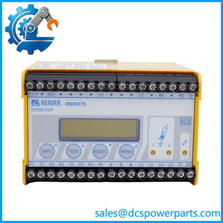
IRDH275B-435W
AMPPlus measurement method
Power-electronic equipment can make insulation monitoring difficult. Rectifiers, converters, thyristor-controlled drives, switch-mode supplies, and EMC suppression components can create leakage capacitance between the electrical system and earth.
The uses Bender’s AMPPlus measurement method and automatically adapts to existing system leakage capacitance. That allows the device to remain useful in installations where a simpler measurement technique could be affected by the electrical characteristics of the connected equipment.
Two independently adjustable alarm thresholds
Two response values from 1 kΩ to 10 MΩ can be set independently. This allows the engineering team to establish separate levels for early warning and more serious insulation deterioration. The two alarm relays can be configured for normally open or normally closed operation.
BMS communication
The includes a galvanically isolated RS-485 interface using Bender’s BMS protocol. This allows the device to exchange information with other compatible Bender devices instead of operating only through its local display and relay contacts.
The isolation of the communication interface is worth noting when reviewing the device in an industrial electrical environment. RS-485 should not be assumed to be an ordinary non-isolated serial interface.
Alarm history with real-time clock
The B version incorporates history memory and a real-time clock for storing alarm messages with date and time information. This provides useful troubleshooting information when insulation resistance deteriorates intermittently rather than remaining permanently below the alarm threshold.
For maintenance teams, this can be more useful than a simple relay alarm that only tells the operator that a fault currently exists.
Electrically isolated analog output
The B version provides an electrically isolated 0(4)–20 mA output proportional to the measured insulation value. This can be useful for feeding an analog input on a PLC, DCS, monitoring system, or recorder when a continuous representation of insulation resistance is required.
The exact scaling and configured output behavior should be checked during commissioning rather than assumed from the generic 0(4)–20 mA designation.
High-voltage system coverage
Direct monitoring extends to 793 VAC and 650 VDC. Bender documents the use of external coupling devices when higher system voltages need to be monitored. Suitable coupling hardware depends on the voltage and application.
This is particularly relevant in retrofit projects. If an existing installation exceeds the direct measurement range, changing only the is not a complete solution; the coupling arrangement must be engineered as well.
Two alarm relays
K1 and K2 provide two changeover contacts. K1 corresponds to Alarm 1, while K2 can handle Alarm 2 and device-fault functions. The contacts can be configured for N/O or N/C operation.
For safety-related monitoring, the selected contact logic should be documented in the control-system drawings because the physical relay state alone does not tell you how the application has been configured.
Related Products
- IRDH275-435 — Basic IRDH275 insulation monitor in the same 0–793 VAC / 0–650 VDC monitored-voltage class, but without the additional B-version functionality.
- IRDH275W-435 — W variant of the -435 device with enhanced resistance to mechanical stress and moisture for demanding environments.
- IRDH275BW-435 — B version combined with the W environmental/mechanical option. It retains the BMS and history functions while adding the W designation.
- IRDH275B-427 — Lower-voltage supply variant of the B-series , using AC 19.2–55 V / DC 19.2–72 V supply.
- IRDH275B-425 — Another B-series supply variant intended for the lower auxiliary-voltage range.
- IRDH375B-435 — Related Bender ISOMETER family for panel/door mounting rather than the mounting arrangement.
- IRDH575 — Bender insulation-monitoring family intended for applications requiring different monitoring capabilities, including insulation-fault-location applications.
- isoLR275 — Later Bender insulation-monitoring solution for systems with particularly low insulation resistance and higher DC-voltage capability when used with the appropriate AGH-LR coupling device.
- AGH204S-4 — Bender coupling device for extending the applicable system-voltage range of compatible ISOMETER devices.
FAQ
What does the “B” in mean?
The B identifies the enhanced version. Bender documents the B series as adding a BMS interface, history memory with real-time clock, and other functions including the electrically isolated current output.
What is the difference between and -435?
Both versions monitor the same basic 3(N)AC 0–793 V / DC 0–650 V system range and use the -435 auxiliary supply class. The B version adds RS-485/BMS communication, event history with real-time clock, and the isolated 0(4)–20 mA output.
Can the monitor a 650 VDC IT system?
Yes. The documented direct DC monitoring range is 0–650 VDC. Higher-voltage systems require an appropriate external coupling device rather than simply connecting the directly to the higher-voltage circuit.
Can I hot-swap the ?
This should not be treated as a hot-swappable PLC I/O module. The device is connected directly into the electrical system being monitored and also has an auxiliary supply and alarm/control wiring. Follow the installation procedure, isolate circuits where required, and verify the IT-system configuration before removing the unit.
Does the support RS-485?
Yes. The B version includes a galvanically isolated RS-485 interface using BMS protocol. This is one of the principal differences between the B version and the basic version.
Does the analog output provide 4–20 mA?
The Bender documentation specifies an electrically isolated 0(4)–20 mA current output corresponding to the measured insulation value. The exact output mode and scaling should be checked in the device configuration before integrating it into a PLC or DCS analog-input channel.
Does it support firmware v3.1?
The model number does not establish a firmware version. The manual identifies software information for the IRDH275B, but a specific installed firmware revision should be verified from the actual device rather than inferred from the ordering number.
What supply voltage does the -435 version require?
The -435 version uses an auxiliary supply of 88–264 VAC or 77–286 VDC. This is separate from the monitored system voltage.
Is the suitable for systems with converters and switching power supplies?
Yes. Bender specifically lists AC/DC main circuits containing rectifiers, converters, thyristor-controlled DC drives, and switch-mode power supplies among the intended applications. Its AMPPlus measurement method automatically adapts to existing system leakage capacitance.
Is the same as IRDH275BW-435?
No. The BW version adds the W option. Bender documents the W versions as having improved shock and vibration resistance and enhanced protection of the electronics against mechanical stress and moisture. This is relevant for applications such as ships, rolling stock, and seismic environments.
Procurement Note
When sourcing a , verify the complete designation rather than accepting a generic “” description. The B91065101 ordering number identifies the configuration. The -435 suffix establishes the high-range auxiliary supply, while the B suffix establishes the additional communication, memory, and analog-output functions.
For replacement work, check the monitored system voltage, AC/DC system type, existing alarm thresholds, relay contact logic, BMS network configuration, analog-output wiring, and auxiliary supply before commissioning. If the installation uses a coupling device because of elevated system voltage, verify that device as part of the replacement assessment.
For legacy inventory, request a photograph of the actual nameplate and verify rather than relying on a photograph or description that only says “.” Also distinguish the standard B version from IRDH275BW-435; the latter has the additional W environmental/mechanical specification.
The device should be treated as an insulation-monitoring instrument, not as a conventional PLC protection relay. Its correct operation depends on the electrical topology of the IT system, the configured response thresholds, coupling conditions, and the way its alarm outputs are integrated into the plant’s protection and maintenance strategy.