Description
Key Technical Specifications
| Parameter | Specification |
|---|---|
| Product Model | STI300 |
| Manufacturer | ALSTOM Power Systems |
| Product Type | Shaft-speed measurement / I/O module |
| System Family | ALSPA Series 6 |
| Host Controller | MFC3000 |
| Measurement Purpose | Rotational speed of machine shafts |
| Measurement Channels | 3 channels (CH1, CH2, CH3) |
| Sensor Support | Speed sensors; exact sensor types require configuration verification |
| Sensor Supply | Module provides power to connected measurement sensors |
| Installation | PCB installed in the controller rack |
| Front-Panel Connections | External sensor connections and status indicators |
| Software Version | STI300 module software version 1.0 or later, as stated in the measurement-module approval document |
| Communication | Internal MFC3000 controller interface; external protocol not verified |
| Supply Voltage | Not independently verified |
| Operating Temperature | Not verified |
| Protection Rating | Not verified |
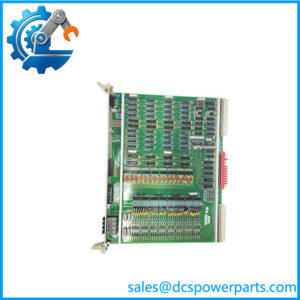
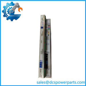
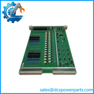
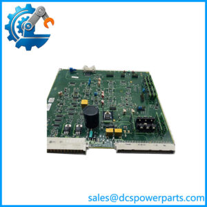
The MFC3000 manual identifies the STI300 as its I/O board and describes three measurement channels. It also documents a dedicated STI300 device-status view for configuration, fault information, parameters, and online values.
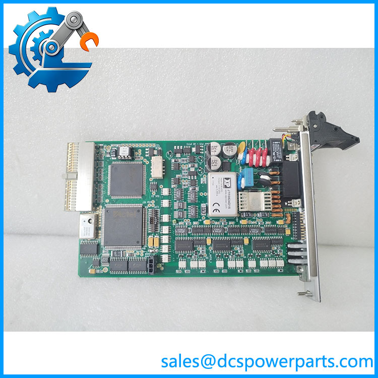
STI300
Product Introduction
The ALSTOM STI300 is a shaft-speed measurement module used in industrial measurement and control systems. In the ALSPA Series 6 architecture, it operates as the I/O board in the MFC3000 controller rack, receiving signals from speed sensors and providing measurement information to the controller. The module also supplies power to connected measurement sensors.
The board has three measurement channels and front-panel connections for external wiring. Its condition and channel status should be checked through the MFC3000 device-status interface. Exact sensor compatibility, electrical input ranges, and supply characteristics should be confirmed against the installed board revision and system documentation rather than assumed from the STI300 designation alone.
Application Scenarios & Field Pitfalls
Typical applications
- Turbine speed monitoring: Measures shaft rotational speed for turbine control and monitoring systems.
- Industrial rotating equipment: Provides speed-sensor measurements for supported machinery monitoring and control applications.
- ALSPA Series 6 control systems: Serves as the measurement I/O board in MFC3000 rack configurations.
- Multi-channel speed acquisition: Uses three measurement channels for supported sensor inputs.
Field checks before replacement
- Confirm the system identity. Verify that the installed unit belongs to an ALSTOM system. is not a unique model designation across all industries.
- Check all three channels. Record the wiring and configured sensor assignments for CH1, CH2, and CH3 before removing the original board.
- Verify sensor compatibility. Confirm sensor type, supply requirements, signal characteristics, and configured measurement thresholds. Do not assume every speed pickup is compatible.
- Inspect the controller slot. The manual specifies the I/O board position in the rack. Do not relocate it based only on physical fit.
- Review diagnostic status. Check initialization, power, channel indicators, and online measurement values before returning the machine to service.
- Validate speed readings. Compare the replacement board’s readings against an independent reference before enabling speed-dependent control or protection functions.
Related Products
- – ALSPA Series 6 controller used with the measurement board.
- ADLink cPCI-3840/AP – CPU board identified in the hardware architecture.
- Hilscher CIF 80-PB – PROFIBUS interface board used in supported configurations.
- ADLink cPCI-8211 – Ethernet interface board used in the controller architecture.
- CP3-QUAD 100TX – Four-port Ethernet board identified in certain configurations.
These are associated controller-system components, not direct replacements for the . Confirm the rack architecture and installed board arrangement before selecting associated hardware.
Procurement and Replacement Notes
When sourcing an , request photographs of the complete board, front-panel connectors, identification label, and PCB revision. Also confirm that the target system is an ALSTOM and record its rack configuration.
A replacement should be checked against the original sensor wiring, channel configuration, and controller diagnostics. Do not use the EPEVER inverter specifications when evaluating the ALSTOM measurement board; they describe an unrelated product.