Description
Key Technical Specifications
| Parameter | Specification |
|---|---|
| Product Model | LC105A-1 |
| Manufacturer | ALSTOM |
| Product Family | ALSPA |
| Associated Systems | P320 / T2000 |
| Product Type | Digital discrete relay output board |
| Output Channels | 16 reported |
| Output Type | Relay contacts, reported |
| Output Contact Rating | Not confirmed |
| Output Voltage | Not confirmed |
| Output Current | Not confirmed |
| Isolation Characteristics | Not confirmed |
| Backplane Interface | Reported P320/T2000 rack backplane |
| Status Indicators | Reported; exact LED functions unverified |
| Supply Voltage | Not confirmed |
| Power Consumption | Not confirmed |
| Operating Temperature | Not confirmed |
| Mounting | Plug-in subrack installation reported |
| Dimensions | Not confirmed |
| Hardware Revision | Suffix -1; revision significance requires OEM confirmation |
Specification caution: Available descriptions consistently identify LC105A-1 as an ALSTOM control board, with several sources describing it as a digital relay output module. However, published secondary listings conflict on its electrical ratings and detailed function. Do not use unverified voltage, current, or contact ratings for field wiring.
Product Introduction
ALSTOM LC105A-1 ALSPA Relay Output Board
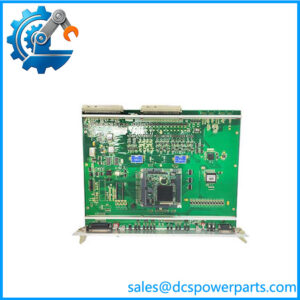
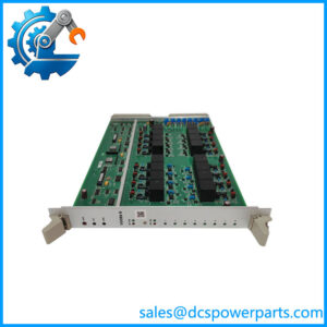
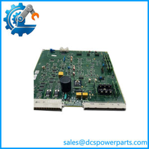
The ALSTOM LC105A-1 is identified as a digital discrete relay output board associated with the ALSPA P320 and T2000 control systems. It is reported to provide 16 relay output channels for transferring controller commands to external field circuits.
In power-generation control cabinets, output-board condition directly affects the execution of equipment commands. Replacement evaluation should include the exact board revision, rack compatibility, relay contact ratings, and field terminal arrangement.
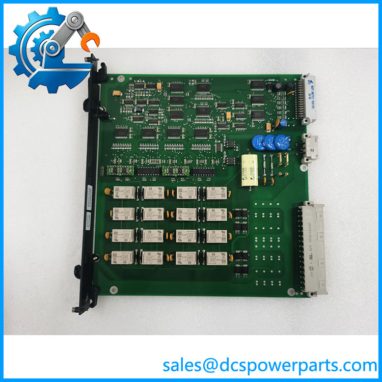
LC105A-1
Application Scenarios & Field Pitfalls (Engineer’s Perspective)
A relay output board fault can appear as an actuator problem even when the field device is functioning correctly. Before replacing the LC105A-1, determine whether the fault originates in the controller logic, backplane connection, output relay, or external wiring.
Potential application scenarios
- Power plant auxiliary control: Relay-based commands for equipment start/stop circuits, subject to the actual system configuration.
- Valve control: Discrete switching signals for external relay or solenoid circuits where the output rating is suitable.
- Equipment status and alarm circuits: Switching contact-based signals in plant control cabinets.
- Legacy DCS maintenance: Replacement of an installed LC105A-1 board in an existing ALSPA P320/T2000 rack.
Field pitfalls to check before replacement
1. Confirm output contact ratings: Do not assume that all LC105-series boards share identical voltage and current ratings. Secondary descriptions distinguish from LC105A-2 and other LC106 variants. Check the original schematic and board documentation before reconnecting field loads.
2. Inspect the backplane and rack connection: Check connector contacts, board seating, rack alignment, and signs of overheating. A defective backplane connection can produce intermittent output faults that resemble a failed relay channel.
3. Verify channel mapping: Record the original channel-to-field-device assignments before removing the board. After installation, perform controlled output testing and verify each affected interposing relay or field circuit. Do not conduct live switching tests without the plant’s approved isolation and commissioning procedures.
Related Products
The following models appear in descriptions of the ALSTOM output-board family or the associated control system. Their functions and interchangeability must be verified individually.
| Model | Description | Relationship |
|---|---|---|
| LC105 | Related digital relay output board; 16 channels and 48 VDC are reported in a secondary description | Base-family reference |
| LC105A-2 | Reported 24 VDC variant of the relay output board | Voltage variant; verify exact rating |
| LC106-1 | Reported non-polarized output module | Related output-board family |
| LC106-2 | Reported non-polarized output module | Related output-board family |
| LE109A-1 | ALSTOM logic controller / CPU board in one product description | Associated control-system component |
| AH901 | Reported power supply module for the LC105 rack family | Power-system relationship |
The descriptions of LC105 and LC106 variants come from secondary technical listings, not a verified OEM interchangeability table.
Procurement and Quality Control Notes
Before ordering an , request:
- Full front and rear board photographs.
- Clear identification of the designation and any additional revision markings.
- Connector and component condition inspection.
- Relay contact testing with documented test conditions.
- Confirmation of the P320/T2000 rack configuration.
- Available functional-test records and repair history.
Replacement recommendation: Do not select LC105A-2 or LC106 variants as substitutes based only on family naming. Their reported output configurations differ, and the actual field voltage and contact requirements must be checked first.
For a more precise specification, a photograph of the nameplate and PCB markings would help distinguish the exact hardware variant.