Description
Key Technical Specifications
| Parameter | Specification |
|---|---|
| Product Model | I/OBE2 |
| Part Number | 12004-104-00 |
| Hardware / Firmware Version | V1.0.0 |
| Manufacturer | ALSTOM |
| Product Type | I/O bus extension / interface board |
| System Architecture | ALSTOM SBS serial-bus remote I/O |
| Form Factor | Eurocard plug-in board |
| Primary Function | Remote I/O bus coupling and data exchange |
| Typical System | Turbine governing / distributed I/O |
| I/O Architecture | Interfaces distributed I/O sub-racks rather than functioning as a standalone PLC |
| Supply | 24 VDC is reported by secondary technical listings; verify against the actual rack/backplane documentation before energizing. |
| Installation | Control rack / Eurocard sub-rack |
| Operating Temperature | Secondary sources report approximately -10°C to +60°C; verify against the system manual for the installed revision. |
The distinction between an I/O bus interface and an ordinary channel-level I/O module matters here. The available technical references describe the I/OBE2 as a communication and bus-extension element within an SBS remote-I/O architecture, while other listings incorrectly assign generic analog/digital channel specifications to it.
Product Introduction
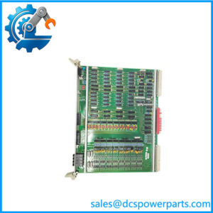
The ALSTOM I/OBE2 12004-104-00 V1.0.0 is an I/O bus extension/interface board associated with ALSTOM SBS serial-bus remote I/O systems. Its role is to provide the communication path between the control-side architecture and distributed I/O sub-racks, allowing field signal data to move between the controller and remote I/O assemblies. The board uses a Eurocard-style plug-in construction and is particularly associated with turbine governing control installations.
For maintenance teams, the important point is that this is not simply a generic replacement I/O card. Its compatibility depends on the complete SBS rack architecture, associated I/O boards, bus configuration, and revision level. When replacing an obsolete board, matching I/OBE2 + 12004-104-00 + V1.0.0 is much safer than selecting a part based only on the I/OBE2 designation.
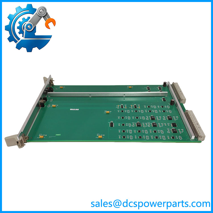
I/OBE2 12004-104-00 V1.0.0
Application Scenarios & Field Pitfalls
Engineering Pain Point
A common maintenance problem with older turbine control systems is that a failed remote-I/O communication board can make an otherwise healthy collection of field I/O modules appear unavailable to the controller. Engineers may initially suspect individual input or output cards, field wiring, or the controller itself.
The I/OBE2 sits at the architectural level where that diagnosis can become misleading. If the SBS communication path is interrupted, multiple downstream I/O points can disappear simultaneously. Replacing individual I/O cards without first checking the bus interface can therefore waste troubleshooting time and introduce additional configuration errors.
Typical Applications
- Steam turbine governing systems — communication between the primary control architecture and distributed I/O racks.
- Combined-cycle power plants — remote I/O interfaces associated with turbine control and auxiliary process equipment.
- Thermal power generation — legacy ALSTOM control cabinets where distributed field signals are concentrated through SBS-based I/O architecture.
- Control-system refurbishment projects — maintaining an existing rack when an original I/ board has failed or become difficult to source.
Technical Pitfalls to Avoid
- Do not treat it as a generic analog/digital I/O card. Some online listings describe this part with generic channel counts and protocols, but the more specific references identify it as an SBS bus extension/interface board. Those generic specifications should not be used for engineering substitution.
- Match the complete identification. Confirm I/, 12004-104-00, and V1.0.0, along with the rack position and adjacent module types. A visually similar Eurocard does not establish functional compatibility.
- Check the bus architecture before commissioning. If the replacement does not establish communication with the downstream I/O rack, investigate rack power, backplane connections, bus termination, cabling, and configuration before assuming the replacement board is defective.
- Do not assume published electrical specifications are authoritative. Public references disagree on several parameters. For a live turbine-control replacement, the installed system documentation and board markings should take precedence over reseller specifications.
Related Products
- ALSTOM I/OBUS2 12004-103-01 V1.2.0 — associated I/O bus interface hardware; useful when checking the upstream/downstream SBS communication architecture.
- ALSTOM VPS 12004-102-03 V1.0.0 — related control-system module appearing within the same family of ALSTOM control hardware.
- ALSTOM STO1726KO1 — associated with the same broader control-system hardware family and commonly referenced alongside I/.
- ALSTOM VIIB16-C 12011-105-00 V1.0.0 — another ALSTOM I/O-related module, but its signal-handling role differs from the I/ bus-extension function.
- ALSTOM DSI1817 TRVC062335000 CP00003934 — pulse-input module used for a different signal acquisition function; it should not be considered a direct I/ substitute.
- ALSTOM POS1846 TRVC062333000 CP00000310 — position detection/control-related I/O hardware serving a different field-interface purpose.
- ALSTOM CMP1838 TRVCO62345000 CP00005202 — CPU/control-oriented module rather than an I/O bus extension board.
Procurement check: For an installed turbine control system, I would treat 12004-104-00 V1.0.0 as the primary identification, not merely “I/.” Before installation, compare the board label, PCB revision, connector arrangement, rack position, and the existing I/OBUS2/SBS architecture against the site documentation. The available public information is not consistent enough to justify a blind substitution.