Description
Product overview
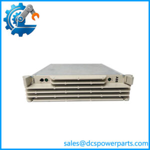
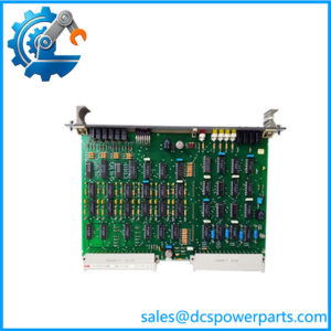
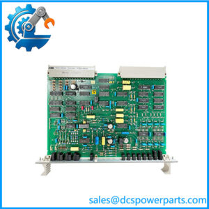
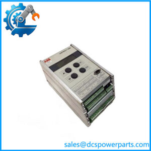
The ABB Bailey SPDSO14 digital output module is an output interface for ABB Symphony Plus and Bailey INFI 90 OPEN distributed control systems. It receives output commands from the control system and switches external digital loads through 16 independently configured, optically isolated open-collector channels. Typical applications include operating interposing relays and other compatible field devices used in process-control sequences. The SPDSO14 is a digital output slave module, not a general-purpose relay card with built-in mechanical contacts.
The module supports loads rated at up to 250 mA at 24 VDC or 125 mA at 48 VDC per output under the documented conditions. It uses a 5 VDC logic supply, with typical current consumption of 275 mA. Field loads are connected through compatible termination hardware: the module can interface with solid-state relays on the NTDO02 termination unit or, where the installation supports it, a relay assembly for electromechanical relays. The termination arrangement matters because the module’s open-collector outputs do not directly provide the same switching behavior as isolated dry relay contacts.
When sourcing the ABB SPDSO14, confirm the module designation, associated termination hardware, output wiring, and control-system configuration. The older IMDSO14 is a related legacy model, and the applicable documentation covers both versions in relevant contexts; nevertheless, verify the specific hardware and application before substituting one for the other. Before returning the module to service, test representative output channels, confirm field-load current requirements, and verify that each command produces the expected response at the connected device.
Product introduction
The SPDSO14 forms part of the Harmony Rack I/O architecture. It exchanges output data with the control subsystem through the I/O expansion bus and routes switched output signals to the external termination assembly. Correct operation depends on the module installation unit, bus connections, termination cabling, and field wiring being configured as intended. A missing or incorrect bus connection can prevent the output subsystem from communicating properly with the controller.
For maintenance or replacement, record the existing module number, slot location, termination-unit model, cable arrangement, and output assignments before removing the card. Inspect the card-edge connectors and front-panel indicators, then perform the manufacturer’s installation and pre-operational checks. Verify each required output against the control logic and the actual field device. Loads exceeding the published channel ratings require a suitable interface or relay arrangement; do not connect them directly based solely on the nominal field voltage.
Key technical specifications
| Parameter | Specification |
|---|---|
| Manufacturer | ABB Bailey Controls |
| Model | SPDSO14 |
| Listed order number | 3BSE010537R1 |
| Product type | Digital output slave module |
| Control-system family | Symphony Plus / INFI 90 OPEN |
| Number of output channels | 16 |
| Output type | Open collector |
| Channel isolation | Optically isolated |
| Maximum load rating at 24 VDC | 250 mA per channel |
| Maximum load rating at 48 VDC | 125 mA per channel |
| Logic supply | 5 VDC ±5% |
| Typical logic-supply current | 275 mA |
| Operating temperature | 0 to 70°C |
| Termination hardware | NTDO02 with solid-state relays, or compatible relay assembly |
| Field wiring | Through compatible termination hardware and cabling |
| Related legacy model | IMDSO14; verify application-specific interchangeability |
| Communication / bus interface | Harmony Rack I/O expansion bus |
| Mechanical dimensions | Confirm against the exact hardware documentation |
| Protection rating | Not verified in the cited ABB catalog entry |
Important: The 24 VDC and 48 VDC values are maximum documented load ratings, not a statement that every output can drive any load type. Check the output circuit, termination assembly, load current, and wiring design before installation.
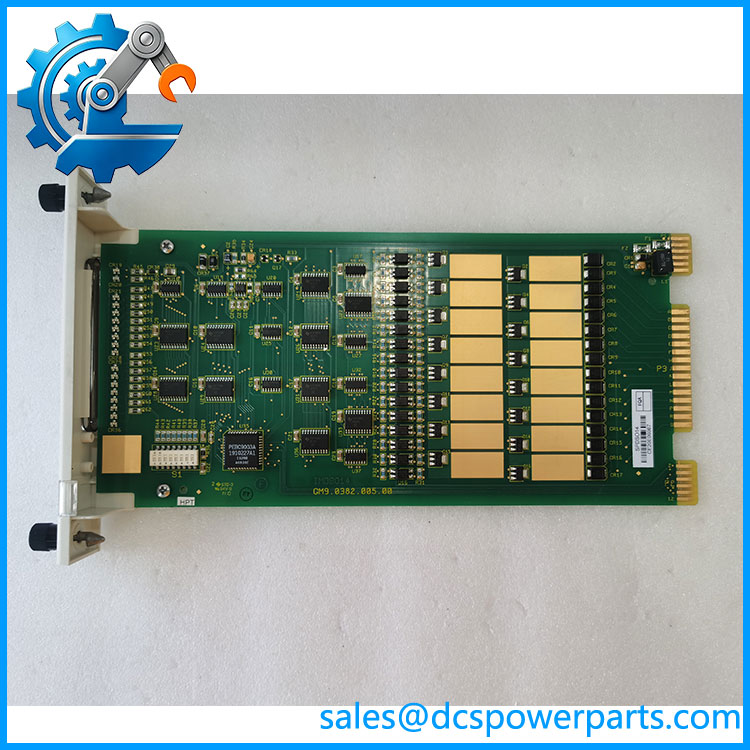
SPDSO14
Related products
- IMDSO14 — Digital Output Module: Legacy Bailey INFI 90 model related to SPDSO14. Verify the exact hardware and application before replacement.
- SPDSO15 — Digital Relay Output Module: A related Symphony Plus output module using relay contacts rather than the open-collector output arrangement.
- NTDO02 — Digital Output Termination Unit: Supports the documented solid-state relay interface for .
- SPDSI14 — Digital Input Module: Handles discrete input signals rather than output commands.
- Symphony Plus Harmony Rack I/O components: The compatible module installation unit, bus connections, and cabling form part of the complete installation.
These products serve different functions and are not automatic substitutes. In particular, a relay-output module should not be substituted for an open-collector module without reviewing the control logic, load circuit, and termination design.
Frequently asked questions
Q1: What is the ABB used for?
It provides 16 digital output channels for ABB Symphony Plus and compatible Bailey INFI 90 OPEN control-system configurations. The outputs switch compatible field loads through an open-collector interface.
Q2: What is the maximum output current?
The ABB catalog lists up to 250 mA per channel at 24 VDC and up to 125 mA per channel at 48 VDC. Confirm that the actual load and termination circuit comply with the module’s electrical limits.
Q3: Does have built-in mechanical relay contacts?
No. Its documented outputs are optically isolated open-collector channels. It can interface with solid-state relays through the NTDO02 or with a compatible relay assembly where the installation supports it.
Q4: Can replace IMDSO14?
The two designations are related, and documentation for the DSO14 module covers both versions in relevant contexts. Confirm the exact replacement approval, hardware configuration, and system compatibility before substituting.
Q5: What power supply does require?
The module requires a 5 VDC logic supply, specified at ±5%, with typical current consumption of 275 mA. This is the module logic supply, not the voltage used to operate the external field loads.
Q6: What should be checked when replacing an ?
Check the complete module identification, installation-unit slot, bus connection, termination unit, cable, field-load voltage and current, and assigned output points. After installation, test the required outputs and confirm the connected devices respond correctly.
Q7: What supplier test evidence is useful?
Request photographs of the actual module and its identification label, a clear condition declaration, and available functional-test records. For used or refurbished modules, ask which channels and operating conditions were tested rather than relying on a generic “tested” statement.
Procurement recommendation
For ABB , the primary procurement concern is matching the output module to the existing I/O architecture and field-load arrangement. Confirm the listed order number 3BSE010537R1 against the actual module label and the plant’s spare-parts documentation before ordering.
Ask the supplier to confirm:
- Exact model and order number.
- Condition: new, unused surplus, refurbished, or used.
- Compatibility with the installed Harmony Rack or INFI 90 configuration.
- Required termination hardware and cable arrangement.
- Available functional-test records and the scope of testing.
- Stock status, dispatch estimate, warranty, and return terms.
Before commissioning, verify the load current for each connected output and test the output-to-field-device response. Correct module identification and documented testing reduce the risk of replacing a failed card with one that is electrically or functionally unsuitable.