Description
Product overview
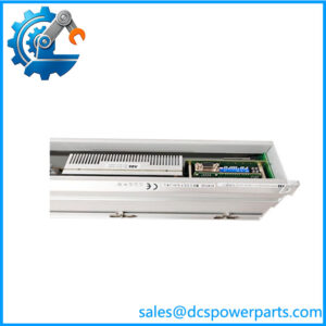
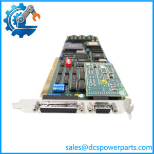
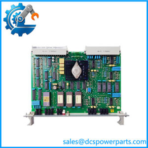
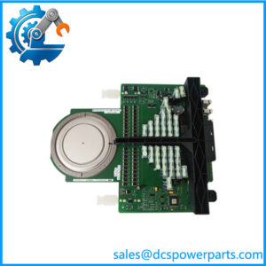
The ABB Bailey SPDSI13 digital input module is designed to acquire discrete field signals for ABB Symphony Plus distributed control systems and supported INFI 90 OPEN installations. It processes up to 16 digital inputs, allowing the controller to monitor binary conditions from compatible field devices such as auxiliary contacts, limit switches, relay contacts, and process-equipment status circuits. Each input channel is optically isolated, helping separate the field signal interface from the module’s internal logic circuitry.
A defining characteristic of the ABB SPDSI13 is its fixed 24 VDC input configuration. ABB specifies a nominal input current of 5.5 mA per channel and a module logic-supply requirement of 5 VDC ±5% at 95 mA typical. These values are important when checking compatibility with the field wiring and the installed I/O system. The SPDSI13 should not be confused with the SPDSI14, which is the 48 VDC variant, or the SPDSI22, which supports a broader range of input voltages. Choosing the wrong version can result in incorrect signal recognition or an incompatible field interface.
For maintenance teams replacing an ABB Bailey SPDSI13, verify the module label, mounting location, input voltage, field common and polarity, and controller configuration before installation. The module’s ability to process 16 inputs does not mean that every field circuit can be connected without checking the associated termination unit and wiring design. After replacement, confirm representative channel states against the actual field devices and verify that the controller receives the expected status changes.
4. Product introduction
The SPDSI13 operates as part of the Symphony Plus HR Series I/O architecture. It converts the electrical states of compatible 24 VDC field signals into digital input information for the controller. Its 16 optically isolated channels support discrete monitoring in process automation, where input states may represent equipment running status, valve position, permissive conditions, or alarms. The module is intended for use within the specified rack and system configuration rather than as a standalone field-mounted input device.
When replacing the module, record the existing slot, module identification, termination arrangement, field wiring, and channel assignments. Confirm that the field signals are 24 VDC and that the selected module matches the installed system. After fitting the replacement, verify input status changes and check that the corresponding controller points update correctly. Troubleshooting should include the field supply, wiring, common connections, termination hardware, and controller configuration—not just the input card itself.
5. Key technical specifications
| Parameter | Specification |
|---|---|
| Manufacturer | ABB Bailey Controls |
| Model | SPDSI13 |
| Product type | Digital input module |
| System family | Symphony Plus HR Series |
| Legacy system compatibility | Supported INFI 90 OPEN configurations |
| Number of input channels | 16 |
| Input type | Digital / discrete |
| Field input voltage | Fixed 24 VDC |
| Nominal input current | 5.5 mA per channel |
| Channel isolation | Optical isolation |
| Module logic supply | 5 VDC ±5% |
| Typical logic-supply current | 95 mA |
| Ambient operating temperature | 0 to 70°C |
| Dimensions (W × H × D) | 35.56 × 177.80 × 298.45 mm |
| Mounting | Compatible Symphony Plus HR Series module mounting |
| Field termination | Verify the applicable termination unit and wiring documentation |
| Response time | Confirm the required response and filtering details in the module manual |
| Protection rating | Not verified in the cited ABB catalog entry |
Technical note: The 24 VDC rating is specific to the SPDSI13. Do not apply the 48 VDC rating of the SPDSI14 or the broader voltage options of the SPDSI22 to this model.
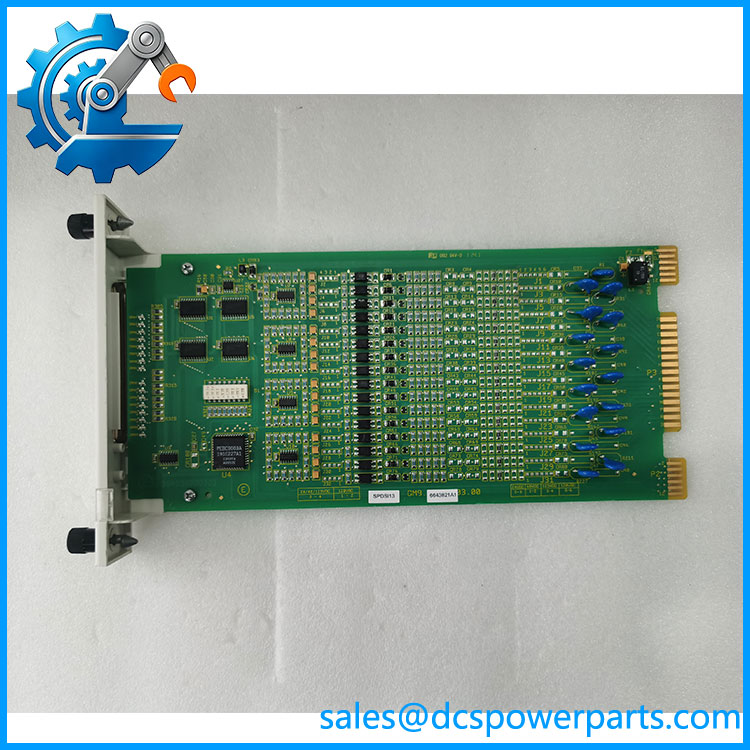
SPDSI13
6. Related products
-
SPDSI14 — 48 VDC Digital Input Module: A related model with a fixed 48 VDC input configuration.
-
SPDSI22 — Multi-voltage Digital Input Module: Supports additional field-voltage configurations, subject to the documented wiring and channel-grouping requirements.
-
IMDSI13 — Legacy Digital Input Module: Related INFI 90 nomenclature; verify the exact replacement requirements for the installed system.
-
NTDI01 — Digital Input Termination Unit: A related termination component referenced in the digital input module documentation.
-
NFTP01 — Field Termination Panel: Used in supported field-termination arrangements.
-
Symphony Plus HR Series mounting hardware: Required for the module’s physical and electrical integration into the system.
These products have different electrical characteristics or functions and are not automatic substitutes. In particular, do not replace SPDSI13 with SPDSI14 or SPDSI22 without checking the field voltage, wiring, termination arrangement, and system documentation.
7. Frequently asked questions
Q1: What is the ABB SPDSI13 used for?
It acquires up to 16 discrete field signals for compatible ABB Symphony Plus and INFI 90 OPEN control-system configurations.
Q2: What input voltage does SPDSI13 support?
The SPDSI13 is designed for fixed 24 VDC field inputs. It is not the 48 VDC version.
Q3: How many input channels does the module have?
It supports 16 optically isolated digital input channels.
Q4: What is its internal power requirement?
ABB specifies a 5 VDC logic supply, with a tolerance of ±5% and typical current consumption of 95 mA. This is the module logic supply, not the field input voltage.
Q5: Can SPDSI13 replace SPDSI14?
Not as a direct, assumption-based substitution. SPDSI13 uses 24 VDC inputs, while SPDSI14 is designed for 48 VDC inputs. Confirm the field circuit and approved system configuration before selecting a replacement.
Q6: Is SPDSI13 compatible with legacy INFI 90 systems?
ABB’s digital input module documentation identifies the SPDSI family as compatible with existing INFI 90 OPEN systems in supported configurations. Verify the exact installation and mounting arrangement before ordering.
Q7: What should be checked before purchasing a replacement?
Confirm the exact model, 24 VDC field input requirement, module mounting arrangement, termination hardware, field wiring, and available inspection or functional-test evidence. Ask the supplier for photographs of the actual module label.
8. Procurement recommendation
When sourcing the ABB Bailey SPDSI13, prioritize exact model identification and confirmation of the 24 VDC input configuration. Before ordering, ask the supplier to provide:
-
Photographs of the module and its identification label.
-
Confirmation of the exact SPDSI13 model and physical condition.
-
A condition declaration: new, unused surplus, refurbished, or used.
-
Available inspection or functional-test records.
-
Confirmation of compatibility with the installed HR Series or INFI 90 OPEN configuration.
-
Stock status, dispatch estimate, warranty terms, and return conditions.
For a live DCS installation, preserve the original channel assignments and verify the field voltage before reconnecting signals. After installation, test representative inputs and confirm the controller receives the correct states before returning affected process functions to service.