Description
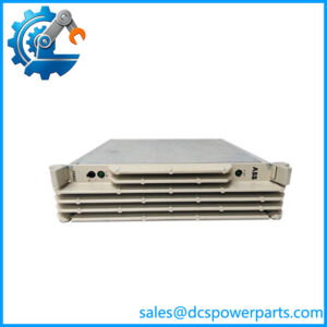
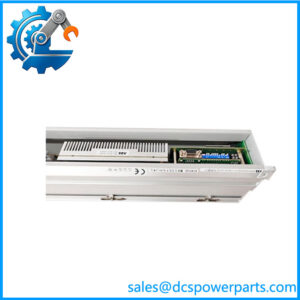
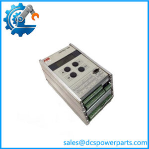
ABB DO05 Digital Output Module
Product Introduction
Relay outputs are still the right choice when a DCS or PLC needs to switch contactors, solenoids, interposing relays, annunciators, or other field loads that do not fit neatly into a low-current transistor output architecture. ABB DO05 is a 16-channel SD Series digital output module built around electromechanical Form C/SPDT relay contacts, with individually isolated channels and selectable normally-open or normally-closed contact behavior.
The practical distinction with ABB DO05 is its switching capacity and relay architecture. ABB rates the contacts for loads up to 3 A under specified conditions, while the module itself requires a 24 VDC supply. It is designed for the Symphony Plus SD Series I/O system and uses compatible HBS/VBS mounting bases rather than functioning as a standalone PLC output card.
Key Technical Specifications
| Parameter | Specification |
|---|---|
| Product Model | DO05 |
| Manufacturer | ABB |
| Article Number | 8VZZ000167H1 |
| Product Family | ABB Ability Symphony Plus SD Series I/O |
| Product Type | Digital Output Module |
| Number of Channels | 16 |
| Output Technology | Electromechanical relay |
| Contact Configuration | Form C, SPDT |
| Relay Coil Voltage | 24 VDC nominal |
| Module Supply | 24 VDC ±10% |
| Module Current | 208 mA maximum; ABB selector also lists 229 mA maximum under detailed data |
| 24 VDC Resistive Load | 3.0 A maximum/channel |
| 24 VDC Inductive Load | 1.5 A maximum/channel |
| 48 VDC Resistive Load | 1.0 A maximum/channel |
| 48 VDC Inductive Load | 0.5 A maximum/channel |
| 125 VDC Resistive Load | 250 mA maximum/channel |
| 125 VDC Inductive Load | 125 mA maximum/channel |
| 120 VAC Load | 3.0 A maximum/channel |
| Minimum Switching Load | 50 mA at 10 V |
| Contact Material | Silver Tin Oxide |
| Contact Life | 100,000 operations |
| Channel Isolation | Individual CH-to-CH galvanic isolation |
| Field-to-Logic Isolation | 1500 V for up to 1 minute |
| Field Cable Length | Up to 600 m / 1968 ft |
| Operating Temperature | -40°C to +70°C |
| Storage Temperature | -40°C to +85°C |
| Relative Humidity | 20–95% at 40°C, non-condensing |
| Form Factor | Standard, 190 mm |
| Dimensions | 27 W × 106 D × 190 H mm |
| Weight | Approx. 295 g |
| Mounting | Horizontal row or vertical column, through compatible SD Series base |
| HART | No |
| SOE | No |
| Redundancy | No |
| Service Interface | Mini-USB / RS-232C service connection |
| Status Indication | Run, Fault, and individual channel LEDs |
ABB’s current Hardware Selector specifies 16 individually isolated electromechanical outputs and gives the detailed resistive/inductive switching limits. The catalog also identifies the module as a standard 190 mm SD Series device.
Application Scenarios & Practical Pain Points
1. DCS Digital Control Outputs
DO05 is suitable where a Symphony Plus controller must operate discrete field equipment through relay contacts. Typical loads can include contactors, motor-control interfaces, solenoid valves, alarm circuits, and interposing relays, subject to the actual voltage, current, and load characteristics.
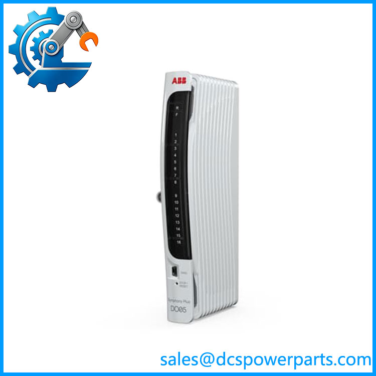
ABB DO05
2. AC Field Switching
The 3 A rating at 120 VAC makes the relay architecture useful for certain AC control circuits. This is one area where DO05 differs materially from many 24 VDC transistor-output modules. The load type still matters; the published rating must not be treated as a universal 3 A rating across every voltage and load category.
3. Mixed NO/NC Control Requirements
The Form C/SPDT relay arrangement provides both normally-open and normally-closed contact options. ABB specifies staple jumpers for selecting NO or NC operation, which is useful when the required field behavior differs between shutdown, alarm, permissive, and normal-running conditions.
4. Legacy Symphony Plus Cabinet Maintenance
For an existing Symphony Plus SD Series installation, replacing the DO module while retaining the established termination architecture can simplify maintenance. The catch is the mounting base: must be installed on a compatible SD Series base, and ABB documents several possible HBS/VBS configurations.
Compatible Mounting Bases
ABB identifies several SD Series bases that can accommodate :
- HBS01-FPH — horizontal mounting base, system-powered field devices with switched-hot configuration.
- HBS01-FPN — horizontal mounting base with switched-neutral configuration.
- HBS01-EPD — externally powered field-device arrangement.
- HBS02-EPD — high-current base specifically documented for , supporting up to 3 A field loads.
- VBS01-FPH — vertical mounting base with switched-hot field power.
- VBS01-FPN — vertical mounting base with switched-neutral field power.
- VBS01-EPD — vertical externally powered configuration.
- VBS02-EPD — vertical high-current base for applications.
ABB specifically identifies HBS02-EPD and VBS02-EPD as high-current mounting bases for , while the broader HBS/VBS family provides several field-power arrangements.
Related Products
- ABB DO01 — SD Series digital output module; different output architecture and ratings, so verify application compatibility rather than assuming interchangeability.
- ABB DO02 — 16-channel digital output module with open-collector outputs and overcurrent/readback functions; it is not a relay-output equivalent to .
- ABB DI01 — SD Series digital input module.
- ABB DI02 — SD Series digital input module.
- ABB DI03 — SD Series digital input module.
- ABB DI04 — SD Series digital input module.
- ABB PI01 — SD Series pulse input module.
- ABB HBS02-EPD — horizontal high-current termination base for .
- ABB VBS02-EPD — vertical high-current termination base for .
ABB’s current SD Series catalog distinguishes from DO02: uses electromechanical relay contacts, while DO02 uses digital open-collector outputs with overcurrent protection and readback. That difference is important during replacement planning.
Engineer’s Guide — Field Pitfalls to Avoid
1. Do not substitute a transistor-output module for
The relay contact is the product’s central electrical characteristic. A transistor output may look similar from the DCS configuration side but behaves differently electrically and cannot provide the same Form C contact arrangement.
2. Check inductive-load current, not just the headline 3 A number
ABB specifies 3 A at 24 VDC for a resistive load but 1.5 A for a 24 VDC inductive load. The distinction becomes important with solenoids, contactor coils, and other inductive devices.
3. Confirm the termination base
A replacement is not complete until the installed base is confirmed. ABB lists multiple compatible HBS and VBS bases, and the field-power arrangement differs between them.
4. Do not confuse 3 A contact rating with module supply current
The output contacts can switch significantly more current than the module’s own 24 VDC electronics supply consumes. The 208/229 mA module-power figures are not field-output current limits.
5. Check relay contact condition on used equipment
For a used , inspect contact wear, evidence of arcing, terminal discoloration, contamination, and mechanical condition. ABB specifies a nominal contact life of 100,000 operations, but that does not mean an unknown used module has that number of operations remaining.
6. Verify the actual switching circuit
The published 125 VDC and 120 VAC ratings have different current limits and load assumptions. If the field circuit is safety-related, high-energy, or highly inductive, validate the complete load circuit against the applicable ABB documentation before installation.
FAQ
What is the ABB ?
ABB is a 16-channel electromechanical relay digital output module in the Symphony Plus SD Series I/O family. It provides Form C/SPDT relay contacts with individual channel isolation.
How much current can ABB switch?
The maximum depends on voltage and load type. ABB specifies up to 3 A at 24 VDC for resistive loads, 1.5 A at 24 VDC for inductive loads, 1 A at 48 VDC resistive, 250 mA at 125 VDC resistive, and 3 A at 120 VAC. These figures should not be generalized across different load categories.
Is a 24 VDC output module?
The module’s electronics are powered from 24 VDC ±10%, but its field outputs are relay contacts rather than fixed 24 VDC transistor outputs. The relay contacts can switch several different AC and DC voltage/current combinations within ABB’s specified limits.
Is ABB compatible with HBS01-FPN?
Yes. ABB identifies HBS01-FPN as a compatible mounting base for and other SD Series digital I/O modules. The FPN configuration uses switched-neutral field power.
What is the difference between and DO02?
uses electromechanical Form C/SPDT relay contacts. DO02 uses open-collector digital outputs and adds output overcurrent protection, monitoring, and readback functionality. They should not be considered electrically equivalent replacements.
Does support HART or SOE?
ABB’s current Hardware Selector lists HART: No and SOE: No for . It is a conventional digital relay-output module rather than a HART or sequence-of-events I/O device.
What should procurement verify before buying an ABB ?
Match the model and article number 8VZZ000167H1, then verify the installed mounting base, field wiring arrangement, relay contact requirements, and module condition. For a used spare, inspect the relay/contact and terminal condition rather than relying solely on the label. ABB currently lists as ACTIVE, so an old inventory listing should still be checked against the current ABB configuration and the physical module marking.