Description
Product Overview
500MTM02 1MRB150020R0712 is the module that brings instrument-transformer signals into a bay control terminal, and its documentation settles a question this family has been carrying since the first number was ordered. The authoritative source is ABB’s own product documentation for the REC 580*3.0 bay control terminal, document 1MRK 511 059-BEN, which names this card plainly: the input transformer module. That supersedes the platform attribution the trade has repeated for these 500xxx designations. They are not Procontrol P13/P14 rack I/O, as supplier listings have long claimed; they are the plug-in complement of a medium-voltage bay controller, sitting in a 21-slot rack on a 500CRB01 or 500CRB02 backplane, alongside a VME-based processor, an MVB process bus controller and a star coupler.
The module’s identity now resolves into four layers, which is one more than the rest of the family carries. 500MTM02 is the module designation; 1MRK001967-AA is the product order code in ABB’s protection-and-control numbering, the same 1MRK style that identifies the terminal family itself; 1MRB150020R0712 is the manufacturing code in the 1MRB block, with R0712 as its release string — and a second release, R1102, circulates for the same base on another page; 1HDF 930512 X010 is the engineering identifier. Four strings, and the one that matters least for buying decisions is the one the market quotes most.
What makes this card genuinely different from every other member of the family is that its specification is not contained in its code. The module is populated at ordering with current and voltage transformers, up to thirteen of them, and each channel is filled with one of three types: a protection-grade current transformer, a metering-grade current transformer, or a potential transformer. Rated voltage is selected from 63.5 V, 110 V or 220 V; rated current from 1 A or 5 A. A channel may also be left empty, which is the provision made for a channel that will instead be fed from the 500ITM02 isolating transducer module or from an optical voltage transducer. Two surplus units bearing the same designation, the same manufacturing code and the same release string can therefore differ in what they measure — one built for a feeder with protection and metering current circuits on separate cores, another built for a busbar with voltage inputs only. That is the single most important fact about buying this module second-hand, and no catalogue in the market mentions it.
The card also cannot stand alone. In ABB’s own configuration notes, 500MTM02 is marked as usable only in combination with a 500AIM02 analog input unit, because the transformer module conditions and scales the signals and the analog input unit digitises them — sixteen channels sampled at 1.0 kHz on a 50 Hz system or 1.2 kHz on 60 Hz, at 6 W. The two are a pair by design, and the terminal’s slot tables reflect it. A related caution appears in the same document and is worth repeating because it is an installation instruction rather than a specification: where both a 500ITM02 and a 500MTM02 sit beside the same analog input unit, the same channel must not be sourced from both.
The trade’s descriptions of this card miss in every direction at once. A communication motherboard; a module with adaptive I²t motor-thermal algorithms that “simulate motor” behaviour; a DCS system CPU module; a bus terminal module; a controller module; and a power module, that last one from a catalogue that files unrelated modules under one heading. Six identities, none of them transformer-related, and the only description that lands anywhere near the truth — measuring transformer module — comes from a single seller who happened to read the function off an older ABB page. The lesson is not that the market is careless about this family in particular; it is that a card whose real specification lives in its ordering configuration cannot be described by anyone who has only seen its part number.
Technical Specifications
| Parameter | Value |
|---|---|
| Module designation | 500MTM02 |
| Product order code | 1MRK001967-AA — ABB protection-and-control numbering |
| Manufacturing code | 1MRB150020R0712 — base 1MRB150020, release R0712; R1102 also circulates for this base |
| Engineering code | 1HDF 930512 X010 |
| Module type | Input transformer module — instrument-transformer interface for the bay control terminal |
| Platform | REC 580*3.0 bay control terminal, ABB document 1MRK 511 059-BEN |
| Backplane / rack | 500CRB01 or 500CRB02, 21 slots; rack 483 × 266 (6U) × 320 mm |
| Current inputs | 1 A or 5 A, 50 or 60 Hz; burden ≤0.05 VA per input at In |
| Current thermal rating | Continuous 4×In; 10 s 30×In protection / 10×In metering; 1 s 100×In protection / 40×In metering; 250×In half-cycle |
| Current accuracy | Protection ±0.5 % of In over 0–1.2 In; metering ±0.2 % of In over 0–1.2 In |
| Voltage inputs | 63.5 V, 110 V or 220 V; burden ≤0.15 VA per phase at Un; accuracy ±0.2 % Un over 0.8–1.2 Un; thermal 2×Un continuous, 3×Un for 10 s |
| Transformer complement | Up to 13 transformers; each channel populated at ordering as pt, mct or pct; rated V and A stated at ordering |
| Companion requirement | Only in combination with 500AIM02; an empty channel is the provision for 500ITM02 or optical voltage transducer supply |
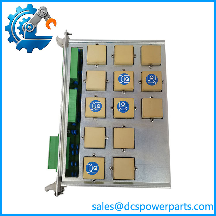
500MTM02
Key Features and Advantages
A documented identity instead of a claimed one: ABB’s own REC 580 documentation names this card as the input transformer module. The platform question that has followed these 500xxx numbers is closed.
Configuration carried in the order, not the code: up to thirteen channels, each a protection CT, a metering CT or a potential transformer, at 63.5/110/220 V and 1 A or 5 A. Two units with identical codes can measure different things — the ordering record is the specification.
Two accuracy classes in one card: protection cores at ±0.5 % of In and metering cores at ±0.2 % of In, both specified over 0–1.2 In, with voltage channels at ±0.2 % Un. That separation is why the module is ordered per channel rather than bought by type.
Thermal headroom built for fault currents: 100×In for one second and 250×In half-cycle on protection cores, against 40×In for one second on metering cores — the physical reason protection and metering circuits are not interchangeable.
A companion fixed by design: 500AIM02 digitises what this card conditions, sixteen channels at 1.0/1.2 kHz. Ordering the transformer module without the analog unit leaves half a measurement chain.
Four identity layers for one card: designation, 1MRK product code, 1MRB manufacturing code and 1HDF engineering code — with two release strings (R0712, R1102) circulating for the same base.
Applications
Medium-voltage bay control in substations: the REC 580 terminal is built for feeder, busbar and transformer bays, and this module is where the bay’s currents and voltages enter it — the point at which the single-line diagram becomes data.
Protection and metering on separate cores: because the module accepts both protection-grade and metering-grade current transformers, one feeder’s protection circuits and its revenue or indication metering can be landed on the same card without compromising either accuracy class.
Retrofit and life extension of installed bays: REC 580 installations remain in service well past their vendor’s product cycle, and a replacement transformer module is normally the consequence of a failed channel rather than a failed card.
Configuration-matched spare holding: the practical application of this module is less about function than about fit — a spare is only a spare if its channel population matches the bay it will serve, which makes the ordering record more valuable than the part itself.
Extension racks and distributed arrangements: where an installation was extended into a second rack joined over the MVB process bus, transformer and analog modules are what the extension carries, with the bus controller and star coupler left in the basic rack.
Where it does not fit: motherboard duty, motor thermal protection, processor duty, bus terminal duty, power supply duty. 500PSM02 and 500PSM03 are the terminal’s supply modules, which is the documentation’s own answer to the power-module labels the trade applies so freely.
Related Products
500AIM02 (16 channels, 1.0/1.2 kHz) — the mandatory companion; the analog input unit that digitises this module’s conditioned outputs, and the reason the two are ordered together. 500ITM02 — the isolating transducer module for small signals, ±5 mA, ±20 mA and ±10 V, with 3, 8 or 16 channels; it may feed a channel left empty on this card, and must not share a channel with it. 500CPU03 — the terminal’s processor module, controller of the internal VME bus with two Industry Pack sockets for the bus interfaces. 500MBA02 — the MVB process bus controller module, with its own processor; the family’s bus role occupied, as the naming implies. 500SCM01 — the star coupler module, converting electrical bus signals to optical across five transmitter/receiver pairs, 3.5 W. 500PSM02 / 500PSM03 — the terminal’s DC/DC supply modules, 60 W and 100 W, input 36–312 V DC; the modules that own the power role. 500BIM01 / 500BOM01 — 24 opto-coupled binary inputs and 22 contact outputs, six with trip-coil supervision; the terminal’s discrete complement. 500CRB01 / 500CRB02 — the two 21-slot backplanes that determine which modules can be fitted where. 500PBI01 / 500LBI02 — the MVB process-bus and LON station-bus interfaces, fitted in the processor’s Industry Pack sockets.
Installation and Maintenance
Before installation: the ordering configuration decides whether the card fits the bay, so match it channel by channel against the single-line diagram — which cores are protection CTs, which are metering CTs, which are potential transformers, at what rated current and voltage, and which channels were deliberately left empty. Confirm the companion 500AIM02 is present in the rack, because the transformer module is documented as usable only with it. Verify the identity strings against the plant’s records, and read the rack’s slot table rather than assuming the card can go anywhere in the 21 slots.
Installation: this card sits on the boundary of two circuit classes that are dangerous in opposite ways. Never open-circuit a current-transformer secondary while primary current can flow, and never short-circuit a voltage-transformer secondary — the first destroys insulation and injures people, the second removes a protection function without any alarm. With the bay isolated and the circuits proven dead, land cores per the schedule and check burden before energising: the module’s ratings assume ≤0.05 VA per current input and ≤0.15 VA per voltage phase, and added burden degrades accuracy rather than failing outright. Where a 500ITM02 shares the analog unit, verify that no channel is fed from both.
Maintenance: accuracy is the parameter that drifts silently, so periodic injection testing against the original commissioning values is the only way to detect degradation before it affects a protection decision. Inspect terminations for thermal damage on current circuits, check that empty channels have not been accidentally landed, and keep the ordering configuration record with the module. A replacement 500MTM02 chosen on designation alone may fit, energise and measure the wrong quantity — the configuration is the specification.
Warranty and Quality
Every 500MTM02 1MRB150020R0712 module is supplied as an input transformer module of ABB’s REC 580 bay control terminal, documented by designation, the 1MRK001967-AA product order code, the 1MRB150020R0712 manufacturing code and the 1HDF 930512 X010 engineering code. Units are inspected for transformer and terminal condition, winding and core evidence of thermal stress, backplane-interface condition, PCB damage, corrosion and label legibility; verification covers the transformer population actually present, insulation between channels, and continuity of each populated channel where test facilities allow. The module’s channel configuration — protection CT, metering CT or potential transformer per channel, and the rated currents and voltages — is reported from the unit’s own markings and ordering record rather than inferred from the code, because the code does not contain it. Electrical data is quoted from ABB’s own documentation for the REC 580 terminal, document 1MRK 511 059-BEN: current inputs 1 A or 5 A with burden ≤0.05 VA at In, voltage inputs 63.5/110/220 V with burden ≤0.15 VA per phase, protection accuracy ±0.5 % of In and metering ±0.2 % of In over 0–1.2 In. A 12-month repair, replacement or refund commitment applies, subject to the configuration match being confirmed against the bay it will serve. Technical support covers what this part actually requires: reading the channel population from the unit itself, confirming the 500AIM02 companion requirement, respecting the rule that a channel must not be sourced from both 500ITM02 and this module, and distinguishing R0712 from the R1102 release also circulating for the same base.