Description
Product Overview
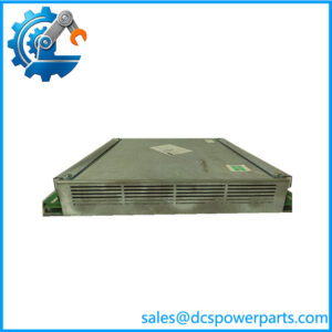
Ordering 500MTM02 1MRB150020R1102 after the R0712 release is the most useful thing that has happened to this family’s decoding, because it puts two release strings side by side on one module and lets them be compared. Both carry the same engineering identifier, 1HDF 930512 X010. Every catalogue page for either release — and there are several for each — prints that identical 1HDF string alongside its own 1MRB number. The hardware does not change between the two; only the release field does.
That single comparison overturns a rule this family has been read with, and the correction is worth stating plainly because earlier readings in this series got it wrong. Where a module appeared under two release values, the assumption was that the difference marked a hardware revision — one card superseding another. The evidence now says otherwise. On the analog input unit 500AIM02, releases R001, R0002 and R0002Y all carry the same 1HDF930412X010; here R0712 and R1102 carry the same 1HDF930512X010. In every case where multiple releases are documented, the engineering code stays fixed while the release number moves, sometimes by a small increment and sometimes by a jump of four hundred. The working rule that survives is this: the 1HDF code identifies the hardware, and the 1MRB release identifies the edition — a manufacturing or documentation issue, not a different card. Two releases of this module are the same module built under two issue regimes.
The practical consequence is a change in what a buyer should worry about, not an increase in worry. Release matching drops from a primary check to a bookkeeping note: a cabinet record that says R0712 and a stock unit marked R1102 describe one hardware design, and the difference does not itself justify rejecting the unit. What does justify rejecting it is the thing no release field can tell you, which is the transformer population. This module is filled at ordering, channel by channel, with protection-grade current transformers, metering-grade current transformers or potential transformers, up to thirteen of them, at 1 A or 5 A and 63.5 V, 110 V or 220 V, with any channel allowed to be left empty for supply from the 500ITM02 isolating transducer module or from an optical voltage transducer. A R1102 card built for a busbar with voltage inputs only is not interchangeable with a R0712 card built for a feeder with protection and metering cores, and the release numbers say nothing about either. The configuration is the specification; the release is an administrative trace.
The pairing requirement from ABB’s own documentation still binds both releases equally. 500MTM02 is usable only in combination with a 500AIM02 analog input unit, which digitises what the transformer module conditions — sixteen channels, sampled at 1.0 kHz on 50 Hz systems and 1.2 kHz on 60 Hz, drawing 6 W. Where a 500ITM02 and a 500MTM02 sit beside the same analog unit, no channel may be sourced from both. Those are configuration rules of the terminal, and they apply to every issue of the card.
The market’s descriptions of the R1102 release are, if anything, more inventive than those of its predecessor. Adaptive I²t motor-thermal modelling on the R0712 pages becomes full motor diagnostics here — stator winding analysis, rotor bar assessment, misalignment detection — on a card that measures currents and voltages through instrument transformers. Other pages call it a power control module with power-status monitoring, a communication motherboard and main control board, an I/O module, and a controller module. And one listing page for this exact string carries the technical data of a different module altogether, quoting 500PSM03 1MRB150038R0001, a 0 to +50 °C temperature range and a 4.4 cm height — a supply module’s data sitting under a transformer module’s URL. That last example is the most instructive of the group: it shows these pages are assembled from whatever strings the seller has on hand, and that a page can be correct about a part number and wrong about which product the number belongs to.
ABB’s documentation for the REC 580*3.0 terminal, 1MRK 511 059-BEN, is what makes this order readable at all. It names the card as the input transformer module, sets out its transformer selection table for ordering, its accuracy classes and thermal ratings, its slot provisions in the two 21-slot backplanes, and the companion rules. Everything specific in this article comes from that document; everything the trade adds is either generic or false.
Technical Specifications
| Parameter | Value |
|---|---|
| Module designation | 500MTM02 |
| Manufacturing code | 1MRB150020R1102 — base 1MRB150020, release R1102 |
| Sibling release | 1MRB150020R0712, the same base and the same engineering code — one hardware design, two editions |
| Product order code | 1MRK001967-AA — ABB protection-and-control numbering |
| Engineering code | 1HDF 930512 X010 — the hardware identity, unchanged across both releases |
| Module type | Input transformer module — instrument-transformer interface for the bay control terminal |
| Platform | REC 580*3.0 bay control terminal, ABB document 1MRK 511 059-BEN |
| Backplane / rack | 500CRB01 or 500CRB02, 21 slots; rack 483 × 266 (6U) × 320 mm |
| Current inputs | 1 A or 5 A, 50 or 60 Hz; burden ≤0.05 VA per input at In |
| Current thermal rating | Continuous 4×In; 10 s 30×In protection / 10×In metering; 1 s 100×In protection / 40×In metering; 250×In half-cycle |
| Current accuracy | Protection ±0.5 % of In over 0–1.2 In; metering ±0.2 % of In over 0–1.2 In |
| Voltage inputs | 63.5 V, 110 V or 220 V; burden ≤0.15 VA per phase at Un; accuracy ±0.2 % Un over 0.8–1.2 Un; thermal 2×Un continuous, 3×Un for 10 s |
| Transformer complement | Up to 13 transformers; each channel populated at ordering as pt, mct or pct, with rated V and A stated at ordering |
| Companion requirement | Only in combination with 500AIM02; empty channels are the provision for 500ITM02 or optical voltage transducer supply |
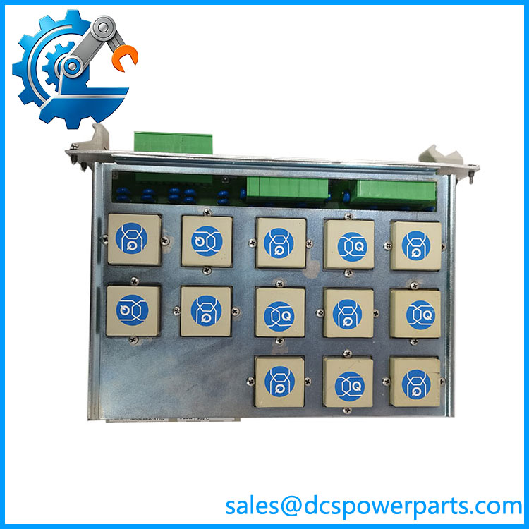
500MTM02 1MRB150020R1102
Key Features and Advantages
Two releases, one hardware identity: R0712 and R1102 both carry 1HDF 930512 X010. The engineering code, not the release, is the discriminator.
A rule corrected by evidence: on 500AIM02, three releases share one 1HDF code; here two releases share another. Releases move in editions, so a stock unit at a different release is a different edition of the same card, not a different card.
The real fit question is configuration, not code: thirteen channels, each a protection CT, a metering CT or a potential transformer, at 1 A or 5 A and 63.5/110/220 V. A spare matches a bay only if its population matches the single-line diagram.
Two accuracy classes on one card: protection cores at ±0.5 % of In, metering cores at ±0.2 % of In over 0–1.2 In, voltage channels at ±0.2 % Un — specified per core because the cores are ordered per channel.
Fault-current headroom carried in the ordering: 100×In for one second and 250×In half-cycle on protection cores, against 40×In for one second on metering cores. The two are not interchangeable even when they sit on the same card.
Documentation instead of description: the REC 580 manual supplies channels, accuracy, thermal ratings, slot provisions and companion rules, while the trade supplies motor diagnostics, power control and — on this exact string — another module’s temperature range and height.
Applications
Feeder and busbar bays in medium-voltage substations: the point where a bay’s currents and voltages enter the bay control terminal, and where the single-line diagram becomes measurable data.
Combined protection and metering on one card: separate protection-grade and metering-grade cores let one feeder serve both a protection function and a metering function without either accuracy class being compromised.
Replacements driven by a single failed channel: transformers fail individually rather than wholesale, so the demand for this module is usually a channel-level fault — which makes an exactly configured spare more valuable than a newer edition of a differently configured one.
Extension and distributed arrangements: where a second rack was added over the MVB process bus, transformer and analog modules are what the extension carries, while the bus controller and star coupler stay in the basic rack.
Stock rationalisation after a fleet of REC 580 terminals: several bays, several configurations, one designation — which is precisely the situation where release numbers get noticed and channel populations get overlooked.
Where it does not fit: motor diagnostics, motor thermal protection, power control or power supply duty (500PSM02 and 500PSM03 are the terminal’s supply modules), communication motherboard duty, controller duty, or plain I/O duty. None of those descriptions survives contact with ABB’s own module list for the terminal.
Related Products
500AIM02 — the mandatory companion analog input unit, 16 channels at 1.0/1.2 kHz, 6 W; the card without which this module has nowhere to send its signals. 1HDF 930512 X010 — this module’s engineering identifier, the string that stays constant while releases move; the layer to compare when two stock units are candidates. 500ITM02 — the isolating transducer module, 3/8/16 channels of ±5 mA, ±20 mA and ±10 V; it may feed a channel left empty here, and must never share a channel with this card. 500PSM02 / 500PSM03 (1MRB150038R0001) — the terminal’s DC/DC supply modules, 60 W and 100 W, 36–312 V DC input; the modules that own the power role, and the ones whose data a listing page for this card mistakenly quotes. 500CPU03 — the terminal’s processor module with two Industry Pack sockets; controller of the internal VME bus. 500MBA02 — the MVB process bus controller module, with its own processor and 3 W consumption. 500SCM01 — the star coupler module, five optical transmitter/receiver pairs converting electrical bus signals to fibre. 500BIM01 / 500BOM01 — 24 opto-coupled binary inputs and 22 contact outputs, six with trip-coil supervision. 500CRB01 / 500CRB02 — the 21-slot backplanes that determine where in the rack each module may sit.
Installation and Maintenance
Before installation: compare the transformer population against the single-line diagram, channel by channel — protection CT, metering CT or potential transformer, at which rated current and voltage, and which channels were deliberately left empty. Treat the release number as a note rather than a gate: a unit and a unit share 1HDF 930512 X010 and the same hardware. Confirm the 500AIM02 companion is present in the rack, and check the slot provisions in the terminal’s tables rather than assuming any free slot will do.
Installation: the circuits this card lands are the two that fail catastrophically when handled wrongly. A current-transformer secondary must never be open-circuited while primary current can flow, and a voltage-transformer secondary must never be short-circuited — the first destroys insulation and endangers people, the second silently disables a protection function. With the bay isolated and circuits proven dead, land cores per the schedule, then check burden before energising: the ratings assume ≤0.05 VA per current input and ≤0.15 VA per voltage phase, and excess burden degrades accuracy quietly instead of failing. Where a 500ITM02 shares the analog unit, verify that no channel is fed from both sources.
Maintenance: injection testing against commissioning values is the only method that catches accuracy drift before it changes a protection decision. Inspect current-circuit terminations for thermal damage, confirm empty channels have stayed empty, and record the module’s configuration alongside its 1HDF code and release — the release for traceability, the configuration for function. Store spares labelled by transformer population first and by code second, because that is the order in which they will be needed.
Warranty and Quality
Every 500MTM02 1MRB150020R1102 module is supplied as an input transformer module of ABB’s REC 580 bay control terminal, documented by designation, the 1MRK001967-AA product order code, the 1MRB150020R1102 manufacturing code and the 1HDF 930512 X010 engineering code, with the release recorded as the edition it is rather than as a hardware revision. Units are inspected for transformer and terminal condition, thermal stress evidence on windings and cores, backplane-interface condition, PCB damage, corrosion and label legibility; verification covers the transformer population actually fitted, insulation between channels and continuity of each populated channel where test facilities allow. The channel configuration is reported from the unit’s own markings and ordering record, not inferred from any code. Electrical data is quoted from ABB’s documentation for the REC 580 terminal, 1MRK 511 059-BEN: current inputs 1 A or 5 A with burden ≤0.05 VA at In, voltage inputs 63.5/110/220 V with burden ≤0.15 VA per phase, protection accuracy ±0.5 % of In and metering ±0.2 % of In over 0–1.2 In, up to thirteen transformers. The descriptions circulating for this release — motor diagnostics and stator winding analysis, power control with status monitoring, communication motherboard, controller, I/O module — are noted and rejected against ABB’s own module list, as is the listing page carrying 500PSM03‘s temperature range and height under this card’s part number. A 12-month repair, replacement or refund commitment applies, subject to the configuration match being confirmed against the bay it will serve. Technical support covers what this part actually requires: reading the transformer population from the unit, treating and as one hardware design under two editions, honouring the 500AIM02 companion rule, and keeping a channel from being fed by both 500ITM02 and this module.