Description
Product Overview
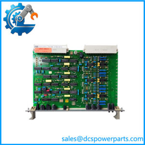
500BOM01 1MRB150023R0002 is the output card this family was visibly missing, and the argument that establishes it is positional rather than verbal. The I/O cluster of the block runs 150022 for the analog module 500AIM02, 150023 here, and 150024 for the binary input module 500BIM01. Adjacent assignments in a factory-planned series usually mean adjacent functions, and 023 sitting directly in front of 024 is where a discrete output card belongs — one number before the input card it faces across the rack. The mechanical and supply-side members are numbered elsewhere: 500MBA01/500MBA02 at 150003 and 500BIO01 at 150005, both at the head of the series. Anything numbered inside the 022–024 run is therefore an I/O card, and BOM reading as binary output module is what the position demands.
That positional argument is what defeats the four other identities in circulation. One catalogue calls it a backboard module and assigns it to the AC500 PLC series; another calls it a power module and, on the same page, lists its “other names” as current controller, input and output module and digital module — four aliases in one listing is not a description but a refusal to commit. A third calls it a drive control/interface board, and the same catalogue elsewhere calls the identical code a motor protection and control relay, which is two different answers from one seller for one number. A fourth attaches it to the AC500 digital output line. The backplane reading fails first and hardest: this family’s backplane and bus role is already occupied by 500MBA01 and 500MBA02, which the trade itself describes as a main backplane/adapter board, and a rack does not carry two backplanes. The power reading fails on the same positional ground — a supply element would sit with the other supply-side members at 150005, not between an analog input and a binary input.
With this order the family’s discrete I/O becomes a complete triangle, which is the most useful thing a buyer can take from it. 500BIM01 is inputs only at 150024, 500BOM01 is outputs only at 150023, and 500BIO01 is combined input and output at 150005. Three cards, three answers to the same engineering question: dedicated input, dedicated output, or both in one slot. The combined card saves slots; the dedicated pair gives isolation between directions so that a fault in one does not take the other down with it, and it lets a cabinet be expanded in whichever direction is short. Knowing that all three exist changes how a retrofit is planned, because the choice is not forced by availability but by the cabinet’s slot count and the fault-isolation the plant wants.
The electrical data attached to this module is invented, and characteristically so. One page states 16 channels, 24 V DC sourcing (PNP), 0.5 A per channel “with total…” — a specification that breaks off mid-sentence and is labelled “typical configuration”, which is the author admitting it is a guess. Nothing in the accessible record says whether the outputs are transistor or relay, whether they source or sink, how many channels there are or what they can switch. Whether that matters depends entirely on the load: a transistor output driving an interposing relay is a different installation from a relay output driving a solenoid, and a card specified by a guess will be wired by a guess. The cabinet’s wiring schedule, the existing card’s terminal markings and the load list are the three documents that settle it, and all three are on site rather than online.
One transcription detail from this search is worth recording because it concerns the sibling rather than this module. A catalogue lists 500MBA02 twice: once correctly as 1MRB150003R0003 and once as 1MRB150003R000B — a letter B where the release digit 3 belongs. That is the signature of hand transcription: a digit turning into a letter that looks like it, in a field where the value decides compatibility. It is the same class of error as the 160024 block that shook loose from 500BIM01‘s order code, and the same defence applies — check the code against the family sequence and against the board label, not against the page that looks most complete.
Technical Specifications
| Parameter | Value |
|---|---|
| Module designation | 500BOM01 |
| Order code | 1MRB150023R0002 — block 1MRB150023, release R0002 |
| Family | 500xxx rack modules, 1MRB15xxxx block |
| Block position | 150023, directly before the binary input module at 150024, inside the 150022–150024 I/O cluster |
| Function category | Binary output module — discrete field drive from the rack |
| Release format | R0002, matching 500BIM01‘s release field |
| Manufacturer | ABB, Sweden |
| Platform compatibility as stated | Procontrol P13 |
| Output type (transistor or relay), sourcing or sinking | Not published |
| Channel count, current per channel, total rating | Not published; the circulating 16-channel, 24 V DC PNP, 0.5 A figure is unsourced and self-labelled “typical” |
| Mounting | Rack plug-in module; slot per the rack’s layout |
| Load compatibility | To be established from the cabinet’s load list before installation |
| Published documentation | None located at module level |
| Lifecycle status | No end-of-life notice located; supply is dismantled and surplus stock |
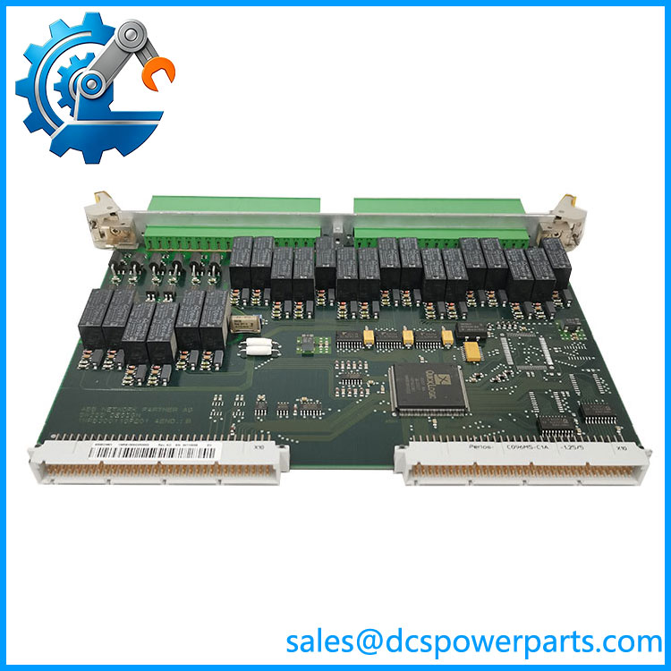
500BOM01 1MRB150023R0002
Key Features and Advantages
An identity argued from position: 150023 sits inside the contiguous 150022–150024 I/O run, while the family’s backplane, bus and supply-side members are numbered at the head of the series. A card inside the I/O cluster is an I/O card, and the name says output.
A complete discrete I/O triangle: 500BIM01 for inputs, 500BOM01 for outputs, 500BIO01 for both in one slot. The choice between dedicated and combined cards is now an engineering decision about slot count and fault isolation rather than a question of what exists.
Sibling releases that agree: this module and 500BIM01 both carry R0002, which places them in the same design generation — a useful pairing when a cabinet is being re-populated from mixed stock.
Four identities retired in one argument: backboard, power module, drive control board and motor protection relay all fail because the roles they claim are either already occupied in this block or numbered outside the I/O run.
A buyer’s caution instead of a specification: output type, polarity and channel count are unpublished, and the one page that offers them breaks off mid-sentence and calls its own numbers “typical”. Whether that card can drive the plant’s load is a site question, answered by the load list.
Transcription awareness: sibling codes in this family are being mangled in exactly the fields that matter — R000B for R0003 on 500MBA02, 160024 for 150024 on 500BIM01. The defence is the sequence and the label, not the page.
Applications
Discrete drive of field devices: indication lamps, interposing relays, annunciator panels and small solenoid or pilot circuits are switched from cards of this class — the point where a control decision becomes an action in the plant.
Annunciation and alarm output: grouping alarm indications onto a panel or into a plant-wide annunciator means many low-current outputs, which is exactly what a dedicated output card is designed for.
Interposing and marshalling of command circuits: where the controller must not switch a heavy or noisy load directly, the output card drives an interposing relay and the plant’s own circuit does the rest — an arrangement that also protects the rack from field transients.
Cabinet expansion in the output direction: plants add trips, alarms and commands more often than they add measurements, which makes output capacity the more frequently exhausted resource and a dedicated card the usual retrofit purchase.
Fault isolation by card choice: separate input and output cards fail independently, so a cabinet that must keep monitoring while its commands are being repaired benefits from the dedicated pair rather than the combined module.
Where it does not fit: backplane or backboard duty, power supply duty, drive control interface duty, motor protection relay duty, or the AC500 digital output line. Each of those has been attached to this number, and each is contradicted by where the card is numbered in its own family.
Related Products
500BIM01 (1MRB150024R0002) — the binary input module at the next block number; this card’s mirror image and the pair a cabinet usually carries together. 500BIO01 (1MRB150005R0001, 1MRB200060/E) — the combined binary input/output module; the slot-saving alternative to this dedicated card. 500AIM02 (1MRB150022R001, 1HDF930412X010) — the analog input module immediately preceding this number; the third member of the I/O cluster. 500TRM02 (1MRB150011R1) — terminal module of the same block; the marshalling element that lands the wiring this card drives. 500MBA01 / 500MBA02 (1MRB150003R0002 / R0003) — the module bus adapters at the head of the series; the cards that already own the backplane role, which is why this module cannot be one. 500CPU05 (1MRB150081R1E) — processor of the same block; the source of the commands this card executes. 500SCM01 (1MRB200059/C, order code 1MRB15004R0001) — a further member of the block listed with its assembly code in the same layered form. 07KT98-H2 (GJR order code) — the older 07KT9x/GJR pattern of the same power-plant control lineage.
Installation and Maintenance
Before installation: establish what the card can switch before it drives anything. Read the cabinet’s load list and the existing card’s terminal markings to determine whether the outputs are transistor or relay, whether they source or sink, and what each circuit draws — because no accessible document states any of it, and the “16-channel, 24 V DC PNP, 0.5 A” figure in circulation is a self-declared guess. Confirm the order code 1MRB150023R0002 against the family sequence and the board label, then verify the slot’s wiring schedule channel by channel.
Installation: with the rack de-energised and field circuits isolated, seat the card to full backplane engagement and land terminations per the schedule. On an output card the discipline is about what the contacts and transistors are asked to survive: verify the load type and current for every channel, fit suppression across inductive loads — coils, solenoids, contactor coils — close to the device, and confirm that no channel is paralleled to share a load beyond what the card permits. After power-up, operate each output into a known load and check the state at the field device, not only at the controller.
Maintenance: expect output channels to fail before input channels do, since they carry the switching duty. Inspect terminations and output devices for signs of heating, check suppression components are still in place after any field work, and log which channels are used so that a spare can be fitted to a known-good slot pattern. When a single channel fails, check the field device and its suppression first; a card that has lost one output usually keeps the others working and gets blamed for a plant fault it did not cause.
Warranty and Quality
Every 500BOM01 1MRB150023R0002 module is supplied as a binary output card of ABB’s 500xxx rack family in the 1MRB15 block, documented by designation and full order code, with the block number verified against the family sequence and the 150022–150024 I/O cluster. Units are inspected for terminal and backplane-interface condition, PCB and assembly damage, rework evidence, corrosion, output-device condition and label legibility; verification covers power-up presence and operation of at least one output into a known load where a compatible rack is available. No channel count, output type, polarity or current rating is asserted, because none is published: the circulating 16-channel, 24 V DC sourcing, 0.5 A statement is labelled “typical” by its own author and breaks off mid-sentence. The backboard, power-module, drive-control-board and motor-protection-relay identities are noted and rejected; the family’s backplane and supply roles are occupied by cards numbered at the head of the series, not inside the I/O run. A 12-month repair, replacement or refund commitment applies. Technical support covers what this part actually requires: distinguishing the dedicated output card from the combined 500BIO01 when either could serve a slot, reading R0002 against a market that mangles digits into letters (R000B appearing for R0003 on a sibling), and confirming the load list before a spare is dispatched.