Description
Product Overview
500BIO01 1MRB150005R0001 is the module in this family that does two jobs in one slot, and the letters now have enough witnesses to say so plainly: BIO reads as binary input/output, a combined discrete card rather than a dedicated input or output unit. Five catalogues converge on that expansion — binary input/output control module, combined binary input and binary output, digital input/output hybrid, digital I/O module — and their descriptions share one revealing sentence: unlike dedicated input or output modules. That phrase is what makes the reading coherent inside this block, because the block already contains a dedicated input card at 150024, 500BIM01. A rack that has BIM for inputs needs something on the output side, and a combined card numbered second in the series is exactly that.
The block numbering, however, needs one correction that this order makes unavoidable. Reading the earlier members, the numbers looked like slot order — coupling at 150003, marshalling at 150011, analog at 150022, digital at 150024, processing at 150081. 500BIO01 at 150005 breaks that reading: it is an I/O card assigned the second-lowest number in the series, ahead of the terminal and analog modules it would share a rack with. The honest conclusion is that these numbers follow design chronology inside the product family, not physical position in a cabinet, and any inference from block number to slot should be dropped. Position 150005 tells you the combined I/O card was conceived early in the family’s development, which is a statement about the product line, not about where the card sits.
The second code is the part of this order that settles a rule the family had only implied. 1MRB150005R0001 is the complete module; 1MRB200060/E is the printed circuit board assembly inside it. That is stated explicitly by one catalogue, and it matches what earlier orders could only suggest — the 1MRB2000xx block seen beside 500MBA01 and 500MBA02 as 1MRB200053 with -L and /M suffixes, and beside 500SCM01 as 1MRB200059/C. The structure is therefore consistent across the family: one 1MRB15xxxx ordering code for the module as delivered, one 1MRB2000xx code for the assembly inside, each carrying a single-letter suffix that distinguishes the build. A buyer who orders the 1MRB2000xx number has ordered the board, not the module — with no housing, no terminals, nothing that makes it a card.
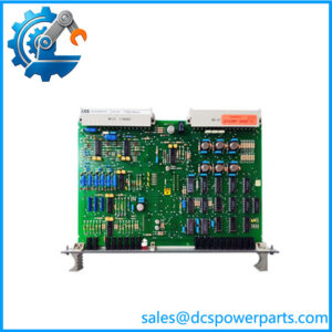
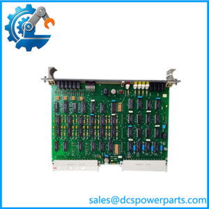
The release field is where this module’s listings become genuinely messy, and the mess has a structure worth naming. This order reads R0001 — release 1, no letter. The market mostly writes R1/J, sometimes R1J, sometimes R1, and one page prints 1MRB150005R0001 beside 1MRB200060-E while another prints R1/J beside 1MRB200060/E. The explanatory reading is that the trailing letter belongs to the assembly layer, not to the release, and sellers habitually glue it onto the end of the order code: R1 plus the assembly’s letter becomes R1/J or R1J. That would make R0001, R1, R1J and R1/J one module with one release and different typography. It is the most economical explanation of four spellings for one item, but it is not confirmed — and the practical rule that survives either reading is simple: photograph the label on the board, because the label carries both codes as the factory printed them, and no reconstruction from catalogue text is as reliable as that.
Two attribution errors round out the picture, and one of them is the most instructive error in this family so far. A catalogue entry sells 500BIO01 1MRB150005R0001 as a Multi Analog Output Module under the brand ICS TRIPLEX. Not a mis-expanded abbreviation, not a wrong platform — an entirely wrong manufacturer, applied to a part whose code structure could not be less ICS Triplex’s. That is the ceiling of what listing-level evidence is worth: when a page cannot get the brand right, its channel counts are worthless too. And the channel counts are, predictably, invented in at least three mutually incompatible ways: nine inputs with six relay outputs; twelve to sixteen inputs with eight to twelve outputs described as “revision dependent”; and a hybrid module with no numbers at all. One page also asserts supply through a “REB500 system backplane”, repeating the busbar-protection attribution that this family has attracted from the start despite having nothing to do with it.
What is real about the card is its role: in a legacy plant rack it is the element that both reads contact states and drives discrete outputs — relays, indication lamps, interposing contacts, small solenoid circuits — from a single slot. That combination is why such cards survive in retrofit inventories: where rack space is fixed and channel counts are modest, one combined card does the work of two.
Technical Specifications
| Parameter | Value |
|---|---|
| Module designation | 500BIO01 |
| Order code | 1MRB150005R0001 — block 1MRB150005, release R0001 |
| Second code | 1MRB200060/E — the PCB assembly inside the module, not the module itself |
| Other spellings in circulation | R1, R1J, R1/J; assembly code also printed as 1MRB200060-E |
| Family | 500xxx rack modules, 1MRB15xxxx block |
| Block position | 150005, second assignment in the series; numbering follows design chronology, not slot order |
| Function category | Combined binary input/output module — discrete read and drive in one slot |
| Manufacturer | ABB, Sweden |
| Platform compatibility as stated | Procontrol P13 |
| Input and output channel counts | Not published; circulating figures of 9+6 and 12–16+8–12 are unsourced |
| Field voltage range, output contact rating | Not published |
| Mounting | Rack plug-in module; slot per the rack’s layout |
| Published documentation | None located at module level |
| Lifecycle status | No end-of-life notice located; supply is dismantled and surplus stock |
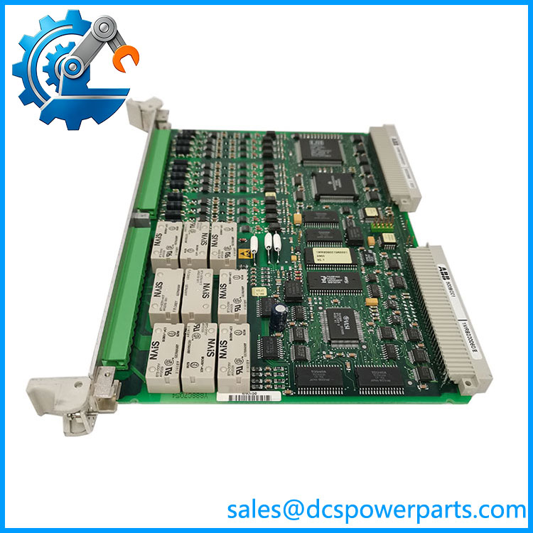
500BIO01 1MRB150005R0001
Key Features and Advantages
Two functions in one slot: BIO as combined binary input/output is supported by five catalogues and by the block’s own composition — a rack that already carries 500BIM01 for inputs needs an output path, and this is it.
The layering rule, finally stated rather than inferred: 1MRB150005R0001 is the complete module, 1MRB200060/E the PCB assembly inside. The 1MRB2000xx block is therefore an internal-build layer across this family, exactly as the -L and /M suffixes on 1MRB200053 suggested.
Four spellings, one release: R0001, R1, R1J and R1/J describe this module in the market, and the most economical reading is that the trailing letter belongs to the assembly and got glued onto the order code. Photographing the board label settles what no catalogue can.
A correction worth carrying: block numbers in this family track design chronology, not cabinet position, as 500BIO01 at 150005 demonstrates. Inferences from number to slot should be discarded.
Brand literacy as a filter: one page sells this part as an ICS Triplex multi-analog output module. A listing that cannot name the manufacturer correctly has no business being believed about channel counts, and that test takes one second.
No invented channel data here: the 9-in/6-out and 12–16-in/8–12-out figures are mutually exclusive, one is hedged as “revision dependent”, and none is documented — so this table says what is known and leaves the rest blank.
Applications
Discrete output driving in plant racks: indication lamps, interposing relays, small solenoid and annunciator circuits are switched from cards of this class, which makes the output side the point where a control decision becomes a physical action.
Combined status-and-command cabinets: where a cabinet both monitors field states and issues discrete commands, one combined card covers both directions — a real advantage in retrofits where slot count is fixed and spares are scarce.
Interlock and permissive chains: inputs certify conditions and outputs release them, so a single card can sit on both sides of a permissive chain — with the caveat that a failed card then affects both directions at once, which is why loop documentation matters more than usual here.
Retrofit of legacy station control: modules in this block are out of production, and the practical risk is a card that fits the socket, matches the name and carries a different assembly build — the layer 1MRB200060/E identifies.
Spares holding against both codes: a store that holds the module code and not the assembly code cannot tell two builds apart when a fault is traced to one direction only.
Where it does not fit: baseplate duty, a multi-analog output module, ICS Triplex equipment, a REB500 backplane, or a dedicated binary input card. The first four are listing errors; the last is what 500BIM01 is for.
Related Products
500BIM01 (1MRB150024R0002) — the dedicated binary input module of the same block; the sibling whose existence defines what BIO adds. 1MRB200060/E — this module’s internal PCB assembly code, also printed 1MRB200060-E; the layer that distinguishes builds, not a substitute order code. 500MBA01 / 500MBA02 (1MRB150003R0002 / R0003) — the module bus adapters at the head of the series, carrying internal codes 1MRB200053-L and 1MRB200053/M in the same layered pattern. 500SCM01 (1MRB200059/C) — a sibling of the same construction, listed with its assembly code in the 1MRB2000xx block; evidence that the layering is family-wide. 500TRM02 (1MRB150011R1) — terminal module of the same block; the marshalling element that lands the field wiring this card reads and drives. 500AIM02 (1MRB150022R001, 1HDF930412X010) — analog input module of the same block; the module that carries a two-block code structure of its own. 500CPU05 (1MRB150081R1E) — processor of the same block; the consumer of this card’s inputs and the issuer of its outputs. 07KT98-H2 (GJR order code) — the older 07KT9x/GJR pattern of the same power-plant control lineage.
Installation and Maintenance
Before installation: photograph the label and read both codes as the factory printed them — 1MRB150005R0001 for the module and 1MRB200060/E for the assembly — because catalogue text spells the release four different ways and no reconstruction is safer than the label. Confirm the cabinet’s record expects this build, then check the slot’s wiring schedule for both directions: input wetting voltage and polarity on one side, output contact rating and load type on the other. A combined card is fitted for two circuits at once, so a mistake in either direction affects a working loop.
Installation: with the rack de-energised and field circuits isolated, seat the card to full backplane engagement and land terminations per the schedule. Verify input polarity at the field side and confirm the output loads are within the contact’s capability before energising — a relay output driving an inductive load beyond its rating fails later, not immediately. After power-up, operate one input and one output against a known field device and check the state in the controller before the cabinet is returned to service.
Maintenance: when a fault appears in one direction only, suspect the field circuit and the terminal block before the card, since a combined module that has lost one direction usually reports the other correctly and gets replaced unnecessarily. Inspect output contacts for pitting where inductive loads are switched, check input terminations for oxidation, and keep the cabinet’s record of module and assembly codes current. Store a spare 500BIO01 labelled with both codes and the direction-specific behaviour observed on test.
Warranty and Quality
Every 500BIO01 1MRB150005R0001 module is supplied as a combined binary input/output card of ABB’s 500xxx rack family in the 1MRB15 block, documented by designation, full order code and the assembly code 1MRB200060/E, so that both layers can be checked against a cabinet record before dispatch. Units are inspected for terminal and backplane-interface condition, PCB and assembly damage, rework evidence, corrosion, output-contact condition and label legibility including both codes; verification covers power-up presence and operation of at least one input and one output against a known device where a compatible rack is available. No input or output channel count, field voltage range or contact rating is asserted, because none is published and the circulating figures — nine inputs with six outputs on one page, twelve to sixteen with eight to twelve described as revision-dependent on another — are mutually exclusive and unsourced. The Multi Analog Output Module listing under an ICS Triplex brand is noted and rejected as a manufacturer misattribution. A 12-month repair, replacement or refund commitment applies. Technical support covers what this part actually requires: keeping the module code distinct from the 1MRB2000xx assembly code, treating R0001, R1, R1J and R1/J as one release until the board label says otherwise, and confirming both the input and output side of the slot before a spare is dispatched.