Description
Technical Specifications
| Parameter | Specification |
|---|---|
| Manufacturer | ABB |
| Product Family | SYNCHROTACT 5 |
| Model | SYN5202A-Z V277 |
| Part Number | Verify: supplied 3BHB0006715R0277; related listings identify 3BHB006715R0277 |
| Product Type | Dual-channel synchronizing device |
| Main Function | Automatic synchronization and paralleling |
| Channel Architecture | Two independent, differently structured channels |
| Auxiliary Supply | 100–230 VAC or 24–250 VDC, subject to exact variant |
| Measuring Voltage | Nominal 50–130 VAC for the documented measuring inputs |
| System Frequency | 50/60 Hz or 16⅔ Hz, depending on configuration |
| Parameter Sets | Up to 7 for applicable configurations |
| Communication | Depends on ordering code and fitted option |
| Mounting | Panel-mounted enclosure for SYN 5202 family |
| Operating Temperature | +5 to +70°C functional range listed in ABB documentation; confirm limits for the exact configuration |
| Protection Rating | Confirm the applicable installation documentation |
Product Overview
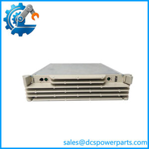
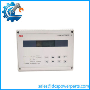
The ABB SYN5202A-Z V277 is associated with the SYNCHROTACT 5 family of synchronization equipment used in generator control and power-system applications. Its primary role is to evaluate synchronization conditions before a generator or electrical source is connected in parallel with a live busbar or another power source. Correct synchronization is essential because differences in voltage, frequency, and phase angle at breaker closing can create electrical and mechanical stress on generators, transformers, circuit breakers, and connected equipment.
Unlike the single-channel SYN 5201, the SYN 5202 uses two independently structured channels within the same device. ABB’s product documentation identifies the SYN 5202 as an automatic dual-channel synchronizing device. The family supports automatic synchronizing and synchrocheck functions, with voltage and frequency matching available for the relevant models. The actual behavior depends on the device type, ordering options, configured parameters, and wiring.
In a typical application, voltage measurement inputs monitor the relevant electrical sources while the configured synchronization logic evaluates whether the conditions for paralleling have been met. Depending on the application and configuration, the equipment can provide adjustment commands and breaker-closing control signals. Commissioning must verify phase sequence, voltage transformer ratios, measurement wiring, breaker feedback, command polarity, and configured limits. A device with the correct model family but incorrect settings or wiring is not a safe substitute for a verified installation.
For procurement, the part number needs special attention. The supplied code 3BHB0006715R0277 differs from the commonly listed 3BHB006715R0277 associated with SYN 5202 equipment. Confirm the full code, suffix, communication option, and auxiliary supply before purchasing. Do not assume that a similar model number establishes full interchangeability.
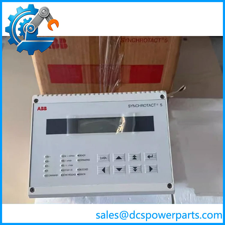
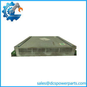
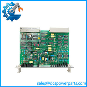
3BHB0006715R0277 SYN5202A-Z V277
Major Features and Advantages
1. Dual-channel synchronization architecture
The SYN 5202 uses two independent channels with different structures. This architecture is intended to support dependable synchronization decisions by reducing reliance on a single processing path. The exact safety behavior depends on the device design and application wiring; it should not be interpreted as a guarantee against every possible failure.
2. Automatic synchronization and synchrocheck
The SYNCHROTACT 5 family supports automatic synchronization and synchrocheck functions. Automatic synchronization can coordinate adjustment commands to bring electrical parameters within configured limits, while synchrocheck evaluates whether the conditions for paralleling are acceptable. The functions available depend on the exact model and configuration.
3. Voltage and frequency matching
Applicable SYN 5202 configurations support voltage and frequency matching. These functions help coordinate generator output with the electrical system before parallel connection. Correct operation depends on measurement circuit design, transformer ratios, configured setpoints, and the connected governor and excitation systems.
4. Multiple parameter sets
ABB’s SYNCHROTACT 5 documentation describes configurations supporting up to seven parameter sets. This allows suitable installations to retain different synchronization settings for multiple paralleling points or operating conditions. The number of sets and their use must be confirmed against the installed ordering code and project configuration.
5. Configurable communication options
The SYNCHROTACT 5 family includes communication options that vary by ordering code, including Modbus, PROFIBUS, LON, and IEC 61850 options across applicable models. Do not assume that every interface is present on the SYN5202A-Z V277. Confirm the option code and actual rear-panel interfaces before designing the connection to a plant control system.
6. Service and commissioning support
ABB documentation describes the SynView PC tool for supported SYNCHROTACT 5 devices. The available service functions depend on the device and communication configuration. Before making changes, record the existing parameters and verify that any service software and connection method are compatible with the installed version.
Typical Applications
- Generator-to-grid synchronization: Assessing electrical conditions before connecting a generator to a live power system.
- Generator paralleling: Supporting controlled parallel connection where the configured device and installation permit it.
- Power plant control systems: Providing synchronization functions alongside excitation, governor, breaker-control, and supervisory systems.
- Industrial captive power plants: Supporting synchronization between onsite generation and an approved electrical bus.
- Multiple paralleling points: Using separate parameter sets where supported and correctly engineered.
- Legacy system maintenance: Replacing or servicing an existing SYNCHROTACT 5 device after verifying the complete ordering code and configuration.
The device is one component of a broader synchronization scheme. Correct operation also depends on voltage sensing, control wiring, breaker mechanisms, interlocks, protection systems, and commissioning settings. A synchronization device does not replace generator protection or the site’s electrical safety procedures.
Related Products
| Model | Relationship |
|---|---|
| SYN5201 | Automatic single-channel synchronizing device in the same SYNCHROTACT 5 family. |
| SYN5202 | Dual-channel synchronizing device family corresponding to the likely identity of the supplied model. |
| SYN5302 | Redundant automatic dual-channel synchronizing device; a different product configuration, not an assumed direct replacement. |
| SYN5100 | Synchrocheck device in the SYNCHROTACT 5 family. |
| SYN5200 | Synchronization/paralleling device family with a different functional configuration from SYN5202. |
| SYN5500 | Related SYNCHROTACT 5 equipment used in supported synchronization system arrangements. |
These models share a product family but have different functions or architectures. Selection or substitution should follow the applicable ABB documentation.
Installation and Maintenance
Before installing the SYN5202A-Z V277, verify the exact ordering code and the installed system’s electrical drawings. Synchronization equipment is directly involved in breaker-closing decisions, so replacing it based only on physical similarity is not sufficient.
- Verify identification: Compare the full product code, suffix, revision, and nameplate with the approved parts list.
- Check auxiliary power: Confirm that the available AC or DC supply is within the rating for the specific variant.
- Validate measurement circuits: Check voltage transformer ratios, phase sequence, polarity, grounding, and measurement wiring against the drawings.
- Review configuration: Back up or document existing synchronization settings before changing or replacing the device.
- Inspect control wiring: Verify breaker-close outputs, voltage/frequency adjustment outputs, breaker position feedback, and required interlocks.
- Test under an approved procedure: Perform commissioning and functional checks under the site’s electrical safety requirements, including verification of blocking conditions.
- Record results: Document the installed part number, parameter set, interface configuration, and test results.
Never bypass synchrocheck interlocks or test breaker-closing commands on a live system without an approved commissioning plan. Follow the applicable ABB operating instructions and plant switching procedures.
Product Assurance
For procurement of the SYN5202A-Z V277, request clear photographs of the nameplate and rear connections, confirmation of the full ABB part number, and a statement of the unit’s condition. For refurbished equipment, request available functional-test records and details of what was tested. A visual inspection alone cannot verify synchronization accuracy, output relay operation, or correct behavior under configured blocking conditions.
Confirm the auxiliary voltage, measuring-input range, communication option, and parameter-set requirements before accepting a replacement. The discrepancy between 3BHB0006715R0277 and the commonly listed 3BHB006715R0277 should be resolved before an order is placed. For a critical generator application, verify the replacement against the existing device configuration and approved engineering documentation.
Procurement recommendation: Treat this as a synchronization-control device, not a generic PLC or I/O module. Confirm the exact ABB ordering code and application configuration before purchase or commissioning.