Description
ABB REB500-BU03 1MRB150071M0001/C Basic Bay Unit
Product Introduction
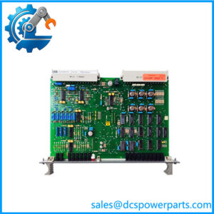
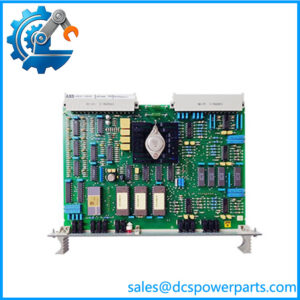
The ABB REB500-BU03 1MRB150071M0001/C is a basic bay unit for ABB’s REB500 distributed busbar protection system. ABB identifies Product ID 1MRB150071M0001 with the type designation REB500-BU03 and catalog description “Basic bay unit.” The BU03 is installed at the individual substation bay and provides the measurement and binary-signal interface between the primary equipment and the REB500 central protection system. In practical terms, it sits much closer to the circuit breakers, CT circuits, isolators, and associated bay wiring than the central processing unit.
The ABB REB500-BU03 1MRB150071M0001/C belongs to a distributed protection architecture intended for fast, selective busbar fault detection. ABB documentation describes the bay unit as the interface between the protection system and the primary process, including main CTs, isolators, and circuit breakers. The architecture uses stabilized differential-current processing together with directional-current comparison, providing high through-fault stability and reduced dependence on extremely high CT performance.
For engineers replacing a ABB -BU03 1MRB150071M0001/C, the important point is that this is not a generic digital relay or PLC I/O card. Its hardware configuration, firmware, CT input arrangement, binary I/O configuration, process-bus addressing, and system project are part of the protection scheme. A physically similar should not be assumed to be a direct replacement without checking the complete type designation and system configuration. Recent documented installations show complete order strings containing firmware and option information beyond the base 1MRB150071M0001 product ID.
Technical Specifications
| Specification | Details |
|---|---|
| Manufacturer | ABB |
| Product Family | |
| Product Type | Basic Bay Unit / Distributed Protection IED |
| Model | – |
| Product ID | 1MRB150071M0001 |
| Supplied Part Number | 1MRB150071M0001/C |
| System Function | Bay-level interface for distributed busbar protection |
| Primary Application | Busbar protection in transmission and distribution substations |
| Protection Principle | Low-impedance busbar differential protection |
| Measurement | Phase-by-phase current measurement |
| Primary Interfaces | CT circuits, breaker signals, isolator/disconnector signals |
| Process Communication | Optical process-bus architecture |
| Central System | Central Unit |
| Protection Features | Differential, stub/T-zone protection and related bay protection functions according to system configuration |
| System Architecture | Distributed bay units plus central unit |
| Mounting | Protection/control cabinet or dedicated bay installation |
| Product Status | Legacy generation; exact lifecycle depends on configuration and installed system |
ABB’s documentation confirms the role and architecture. Exact channel counts, auxiliary supply, terminal arrangement, firmware and option configuration should be taken from the complete type string rather than inferred solely from 1MRB150071M0001/C.
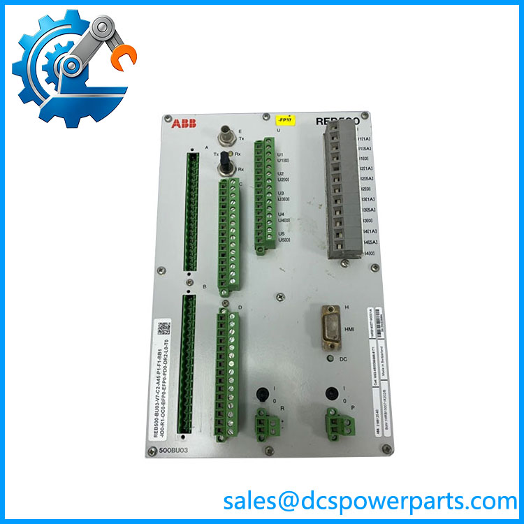
REB500-BU03
Main Features and Engineering Considerations
Distributed Bay-Level Architecture
The main engineering advantage of the architecture is the distribution of measurement functions into individual bay units. The handles the bay-side interface while the central unit coordinates the overall busbar protection system. This reduces the amount of conventional copper wiring that would otherwise have to run from every bay to a central protection panel.
Busbar Differential Protection
is designed around low-impedance busbar protection. ABB documentation describes two independent measurement criteria: a stabilized differential-current algorithm and a directional-current comparison algorithm. The architecture is intended to maintain stability during external faults, including conditions where CT saturation can otherwise create difficult protection conditions.
Primary-System Interface
The provides the interface for signals associated with the bay’s primary equipment. Depending on the specific configuration, this includes current-transformer measurements, circuit-breaker status, isolator/disconnector information and trip/control signals. The exact I/O configuration must be confirmed from the complete order code and project drawings.
Protection-System Integration
The is not normally commissioned as an independent generic protection relay. Its parameters, bay assignment, signal mapping, process-bus configuration and protection logic are tied to the system. A replacement therefore requires both hardware compatibility and project-level configuration compatibility.
Legacy Equipment Consideration
The base 1MRB150071M0001 continues to appear in equipment records, but installations can have detailed version and option strings. For example, documented installations show configurations such as -V7-C1-A40-P0-F1-BB1-IO1-R0-OC0-BFP1-EFP0-PD0-DR0-L0-T0. This demonstrates why matching only the short model designation can be insufficient when replacing an installed unit.
Application Scenarios
High-Voltage Substations
The can be deployed in individual transmission or sub-transmission bays as part of a distributed busbar protection system.
Medium-Voltage and Distribution Substations
The architecture is also applicable to distribution substations where selective busbar fault clearance and bay-level signal processing are required.
Bus Coupler and Feeder Bays
units can interface with feeder, transformer, bus-coupler and related bay equipment according to the system design.
Busbar Differential Protection
The principal application is fast selective detection of internal busbar faults while maintaining security for external faults.
Retrofit Protection Systems
Existing installations may require replacement units during maintenance or hardware refurbishment. In these cases, the original project configuration is as important as the physical module.
Engineer’s Guide: Field Pitfalls
1. Do not treat as a conventional I/O module.
The unit participates directly in a protection scheme. Incorrect configuration can affect protection security and selectivity.
2. Match the complete type designation.
1MRB150071M0001/C identifies the supplied part, but the complete installed type string can contain firmware and functional options. Documented systems demonstrate substantial configuration information beyond the basic Product ID.
3. Verify CT circuits before energization.
CT polarity, ratio, phase identification and wiring continuity must match the protection project’s configuration. A protection relay replacement is not complete merely because all terminals physically fit.
4. Preserve bay assignment.
The replacement BU must correspond to the correct bay within the project. Incorrect bay identification can associate valid electrical measurements with the wrong protection zone.
5. Check process-bus communication.
Optical communication between the bay units and central unit is fundamental to the distributed architecture. Fiber identification, channel assignment and communication status should be checked before protection testing.
6. Confirm breaker and isolator logic.
Busbar protection depends heavily on correct topology information. Incorrect breaker or disconnector status can produce incorrect zone allocation.
7. Do not copy settings blindly between bays.
Two units may have the same hardware family while serving different electrical bays with different CT ratios, breaker arrangements and protection logic.
8. Test the complete protection function.
After replacement, verify current measurement, binary inputs, topology processing, communication with the central unit, trip outputs, alarms and relevant protection functions. For a protection system, functional testing is more important than simply confirming that the unit powers up.
Frequently Asked Questions
W ?
is the Basic Bay Unit used in ABB’s distributed busbar protection system. ABB lists 1MRB150071M0001 as the Product .
Is 1MRB150071M0001/C a PLC?
No. It is a protection-system bay unit / IED used for distributed busbar protection.
What is the main function of the ?
It provides the interface between the bay’s primary equipment and the protection system, including measurement and status information associated with CTs, breakers and isolators.
Is used for busbar differential protection?
Yes. is specifically designed for low-impedance busbar protection, using differential-current and directional-current comparison principles.
Does the work by itself?
It is a component of the distributed architecture. The bay unit interfaces with the primary process while the central unit coordinates the overall protection system.
Is the /C suffix important?
Yes. The supplied part number is 1MRB150071M0001/C, while ABB catalog records identify the base Product ID as 1MRB150071M0001. The /C should therefore be retained when ordering or documenting the exact replacement, rather than assuming that all 1MRB150071M0001 units have identical configurations.
What should be checked before replacing a ?
At minimum, verify the complete type designation, hardware and firmware version, auxiliary supply, CT input arrangement, binary I/O configuration, process-bus connections, bay assignment, protection settings and project configuration.
Procurement Note
For ABB 1MRB1500, the safest procurement description is:
ABB Basic Bay Unit, Product ID 1MRB150071M0001, supplied ordering variant 1MRB150071M0001/C.
For an operational substation, request a clear photograph of the complete nameplate and the full type designation before accepting a substitute. The base Product ID alone does not establish the complete firmware, I/O, protection-function and communication configuration. Documented installations use substantially longer configuration strings containing these details.
Replacement testing should include CT measurement verification, binary-input status, bay topology, process-bus communication, central-unit communication, trip outputs, alarms and the applicable busbar and breaker-failure protection functions before the bay is returned to service.