Description
Technical Specifications
| Parameter | Specification |
|---|---|
| Product Model | CAC 10-P |
| ABB Part Number | 3BDH000610R1 |
| Manufacturer | ABB |
| Product Type | Closed-loop control module |
| System Family | Symphony Plus MR Series / Melody rack |
| Number of Control Channels | 4, independently configurable |
| Supply Voltage | 20–33 V DC |
| Current Consumption | 260 mA at 24 V, without load |
| Maximum Power Dissipation | 13 W |
| Current Output Ranges | 0–20 mA and 4–20 mA |
| Voltage Input Ranges | ±10 V and ±1 V ranges |
| Voltage Output Range | ±10 V |
| Binary Inputs | Four per control channel |
| Power Outputs | Two per control channel |
| Transmitter Supply | Supports two-wire transmitter supply |
| Operating Temperature | 0 to +50 °C, at the specified rack ventilation temperature |
| Dimensions | 40.64 × 311.15 × 160 mm (W × H × D) |
| Required Accessories | Four CI 100/101 units and one cable clamp, according to the product listing |
The electrical data and control-channel functions are based on ABB Symphony Plus MR Series catalog information. Confirm accessory requirements and rack compatibility against the applicable hardware documentation before ordering.
Product Overview
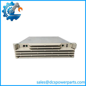
The ABB CAC 10-P 3BDH000610R1 is a four-channel closed-loop control module designed for the Symphony Plus MR Series, also associated with the legacy Melody rack architecture. It is intended for applications where a controller must evaluate feedback signals and adjust an actuator or drive to maintain a target position or process condition. ABB documentation identifies applications including intelligent servo drives, intelligent pneumatic drives, conventional electrical and pneumatic drives, three-point positioners, and step controllers.
Each of the four independently configured control channels provides a combination of analog input, analog outputs, binary inputs, power outputs, a standard binary output, and a supply output for a two-wire transmitter. This arrangement supports closed-loop control tasks that require both continuous signals and discrete operating commands. The exact signal assignments and control strategy depend on the configured application, connected field devices, and system engineering.
The module operates from a 20–33 V DC supply. ABB catalog data lists current consumption of 260 mA at 24 V without load and maximum power dissipation of 13 W. Its analog interfaces support current and voltage signals, including 0–20 mA and 4–20 mA current outputs and specified voltage input and output ranges. These characteristics make it important to check the actual signal type and range of each connected actuator or feedback device before replacement.
For maintenance teams, the most important checks are the exact part number, rack compatibility, installed software configuration, and required accessories. The product listing specifies four CI 100/101 units and one cable clamp as necessary accessories. Confirm the applicable hardware revision and installation documentation to determine the exact requirements for the existing rack. Do not substitute a different MR Series module simply because its physical format or channel count appears similar.
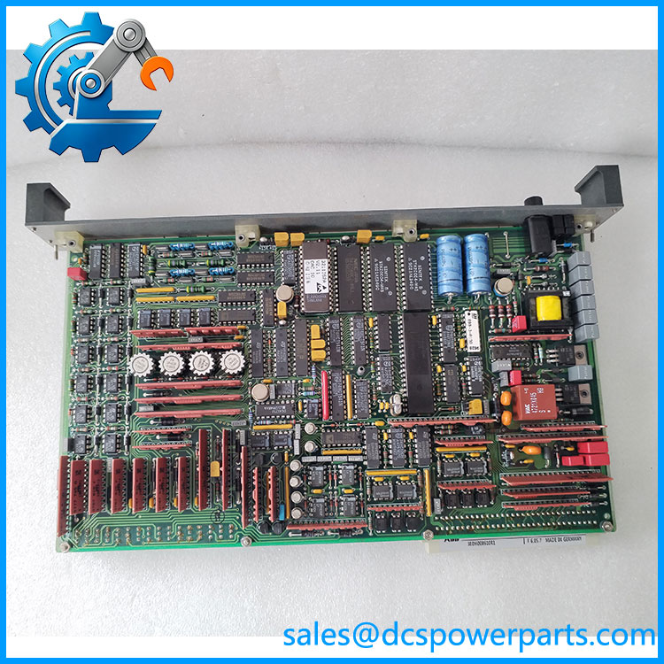
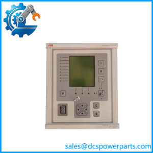
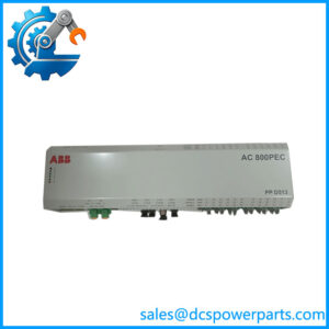
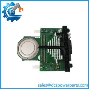
CAC 10-P 3BDH000610R1
Major Features and Advantages
1. Four independent control channels
The CAC 10-P 3BDH000610R1 provides four independently configured closed-loop channels. This supports multiple control tasks within one module, provided the application design and field wiring are appropriate for the required functions.
2. Analog feedback and command signals
The module supports analog input and output signals used in feedback-based control. Its documented current output ranges include 0–20 mA and 4–20 mA, while voltage interfaces support specified bipolar ranges. Correct configuration of signal type and range is essential to avoid incorrect control response or misleading feedback values.
3. Support for discrete field signals
Each control channel includes binary inputs and discrete outputs in addition to analog interfaces. These signals can support operating states and control interactions with compatible field devices. Their exact use must be established from the application configuration and wiring diagrams.
4. Actuator and positioner control
ABB identifies servo drives, pneumatic drives, conventional electrical and pneumatic actuators, three-point positioners, and step controllers as supported application categories. This makes the module relevant to installations where actuator movement must be regulated using feedback rather than controlled only by a simple on/off command.
5. Two-wire transmitter supply
The documented channel arrangement includes a supply output for a two-wire transmitter. Before connecting a transmitter, verify its supply requirements, current draw, signal wiring, and compatibility with the module’s specified limits.
6. Defined power and environmental requirements
The 20–33 V DC supply range and 0–50 °C rack ventilation temperature provide practical installation checks. Cabinet ventilation and power supply capacity should be assessed using the complete rack configuration, not only the module’s nominal consumption.
Applications
The ABB CAC 10-P 3BDH000610R1 is intended for closed-loop control tasks in compatible Symphony Plus MR Series and Melody rack installations. Its applications are determined by the control strategy and field devices connected to the four channels.
- Servo drive control: Applications using feedback and command signals to regulate compatible servo equipment.
- Pneumatic actuator control: Control of compatible pneumatic drives where the application requires continuous regulation or position adjustment.
- Electrical actuator control: Closed-loop control of conventional electrical actuators using supported feedback and output signals.
- Three-point positioners: Applications that use discrete movement commands to adjust a positioner toward a target.
- Step controllers: Control arrangements in which discrete steps are used to adjust an actuator or process variable.
- Process control maintenance: Replacement of a failed module in an existing rack where the original configuration specifies the CAC 10-P.
These examples reflect the application categories documented for the module; they do not guarantee suitability for every actuator, servo drive, or positioner. Engineers should check the required signal ranges, output loading, feedback behavior, and control sequence before selecting the module for a particular loop.
When replacing a module, review the existing control logic and field wiring before making changes. An actuator that receives a valid command can still respond incorrectly if its feedback polarity, signal scaling, or output assignment is wrong. Commissioning should verify both the electrical interface and the complete closed-loop response.
Related Products
| Model / Reference | Relationship |
|---|---|
| CI 100 | Accessory identified in the CAC 10-P product listing; verify the required quantity and revision. |
| CI 101 | Alternative accessory designation listed with the module; confirm the exact requirement in the installation documentation. |
| MR Series rack | Rack family associated with the module’s installation. |
| Symphony Plus | ABB automation platform whose MR Series catalog documents the CAC 10-P. |
| Melody rack | Legacy system designation associated with the product listing. |
| CAO 10-P | Related MR Series analog output module, but not a direct replacement for the CAC 10-P closed-loop control module. |
These are related products, accessories, or system references. They should not be treated as interchangeable with the CAC 10-P 3BDH000610R1 without documented compatibility confirmation.
Installation and Maintenance
Before installing the ABB CAC 10-P 3BDH000610R1, verify the part number against the rack bill of materials and confirm the required accessories. Record the existing channel assignments, analog ranges, binary signal assignments, actuator connections, and application settings before removing the original module.
Isolate the relevant equipment according to the site’s electrical safety procedures. Verify that the DC supply and field wiring meet the module’s documented requirements. Check the rack’s mounting arrangement and ventilation conditions, and make sure the required CI 100/101 accessories and cable clamp are provided where specified.
Inspect connectors and wiring for damage, loose terminals, contamination, or signs of overheating. Confirm that the feedback signal range matches the configured input and that the actuator command interface matches the module’s output type. Do not assume that a module configured for current signals can be exchanged directly into a voltage-signal application without checking the configuration.
After installation, verify the power supply and channel status, then test the connected field devices under an approved commissioning procedure. Check command direction, feedback scaling, response to operating commands, and any configured limits or interlocks. Test each channel individually before returning the controlled equipment to normal service.
Record the replacement part number, channel configuration, test results, and any wiring or settings changes in the maintenance history. If a loop behaves incorrectly, investigate field wiring, feedback devices, actuator mechanics, and configuration settings as well as the control module.
Product Assurance
When sourcing the ABB CAC 10-P 3BDH000610R1, confirm the complete part number, physical condition, and compatibility with the existing MR Series or Melody rack. Verify whether the offered item includes the required accessories or is supplied as the module alone.
The supplier should state whether the item is new, unused surplus, refurbished, or used. Request photographs of the actual label and connectors where possible. If testing is claimed, ask what was tested and whether the checks covered only power-up or also the analog interfaces, binary signals, and closed-loop functions.
A visual inspection alone does not establish functional performance. Where full loop testing is unavailable, that limitation should be disclosed. Confirm return terms and warranty conditions before purchase, particularly when sourcing legacy automation spares.
The documented four-channel control capability and electrical ranges provide a starting point for verification, but the final acceptance decision should be based on the original system configuration, correct accessories, and successful commissioning checks.