Description
Product Overview
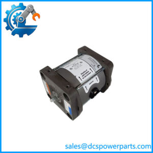
9907-1200 is not an electronic module in the sense the part-number series suggests. It is a hydraulic device with electronics bolted to the top of it: an anodized aluminium housing containing a rotary three-way valve, a brushless limited-angle torque actuator, an internal pressure sensor and a PCB, weighing about 25 kg before any oil reaches it. Its job is to take a 4–20 mA pressure demand from a turbine controller and deliver a proportional, stable oil pressure to a single-acting steam turbine valve servo — the physical link between a control loop running in software and a valve stem moving in a hot, dirty, high-pressure machine room.
The distinction from a conventional I/P converter is the closed loop. A classic current-to-pressure device is open-loop: it converts current to a nozzle-flapper or piezo pressure and hopes the servo agrees. The CPC-II measures its own output pressure with an internal sensor and runs a PID against the demand, so the pressure at the control port is the controlled variable rather than an inferred consequence. That is why the published performance figures are expressed in control terms — pressure stability better than ±2 % of setpoint, accuracy better than ±0.2 % of full range, repeatability 0.1 % of full range, thermal drift under ±0.01 % of full range per °C — and why the device’s response to a step change is measured in milliseconds rather than in seconds.
The model designation carries two facts that a buyer must read correctly. First, 9907-1200 is the 10 bar supply / 10 bar control variant — the low-pressure member of the family, alongside the 25 bar models 9907-1197, 9907-1198 and the redundant 9907-1253 and 9907-1254. The control pressure range is 0 to 10 bar(g), and the recommended maximum setting is below 70 % of supply pressure, so a 10 bar supply supports roughly 6–7 bar of working control pressure with good dynamics. Second, and more consequential, 9907-1200 is the Zone 2 / Class I Division 2 version. Its hydraulically identical twin 9907-1199 carries Zone 1 / Division 1 certification. Same valve, same actuator, same pressure range, different certificate — and that certificate is what decides whether the unit may be installed in the area the plant actually has. Substituting one for the other is not a commercial decision; it is an approval decision.
The construction explains much of its reputation in the field. The hydraulic element is a single moving rotary valve with a self-cleaning port design, driven by a limited-angle torque actuator whose rotor is directly coupled to the valve, with rotor position sensed by a solid-state device reading the shaft magnet. There is one moving part in the oil path and no nozzle to plug. On turbine oil that has seen better days — and turbine oil frequently has — that architecture is the difference between a converter that keeps working and one that silts up and drifts.
Fail-safe behaviour is mechanical, not software. A return spring in the lower cavity moves the valve to port control pressure to drain whenever the unit is unpowered, so loss of electrical supply, pressure-sensor failure or processor failure all drive the control port toward drain and let the valve’s own spring close the steam valve. That is the behaviour a turbine protection philosophy assumes, and it is worth verifying on the bench rather than assuming: de-energise the unit and confirm the control port falls away.
For critical machines the redundancy story is unusually complete for a device of this class. The setpoint input can be configured to accept two 4–20 mA demands and vote between them; the pressure feedback can be taken from the internal sensor or from an external redundant sensor on the same voting logic; and two complete CPC-II units can be arranged as a Master/Slave pair in which the Slave takes control when it detects a Master fault and announces the change on its second discrete output. In a dual arrangement the not-in-control unit has its setpoint deliberately offset so the two valves do not fight each other — a detail that matters when a pair is commissioned by someone who has only read the wiring diagram.
Two commissioning features deserve mention because they are the ones the trade never lists. An eleven-point linearisation table lets the turbine OEM or the plant compensate for a valve whose flow characteristic is non-linear across its stroke, which is the usual reason a perfectly healthy converter produces a sluggish mid-range response. And the silt buster injects a small, symmetrical pressure dither on a configurable schedule — default once a day, 24 ms duration, zero amplitude until it is turned on — specifically to keep the standby unit of a redundant pair from silting while it sits idle.
The market’s descriptions of this part diverge sharply from the manual. One seller calls it a “Speed Control I/O Interface Board for MicroNet Plus” — it is neither an I/O board nor a MicroNet component. Another describes a proportional actuator with LVDT feedback and a supply range of 10 to 207 bar, which conflates this 10 bar device with the 25 bar models and invents a feedback technology the unit does not use. A third correctly lists the 10 bar range, IP66, 290 × 270 × 270 mm and 25 kg but adds an “8 A maximum current output”, which belongs to the older CPC generation’s inrush figure rather than to a control output. What the manual actually says: 25 W steady state, 90 W transient for two seconds, and an analogue output of 4–20 mA into up to 500 Ω.
One more point of housekeeping. Older CPC-II units documented in Manual 26448 are rated IP56; the Enhanced Dynamics generation documented in Manual 26615 and Product Specification 03352 is rated IP66. 9907-1200 sits in the Enhanced list, so IP66 is the correct figure for it — and a spare inherited from an older installation may not be.
Technical Specifications
| Parameter | Value |
|---|---|
| Model | 9907-1200 |
| Manufacturer | Woodward, Inc., Fort Collins, Colorado, USA |
| Product type | Current-to-pressure converter (electrohydraulic), Generation II, enhanced dynamics |
| Family | CPC-II; low-pressure group with 9907-1199, 9907-1228, 9907-1349 |
| Supply pressure | 10 bar / 145 psi |
| Control pressure range | 0 to 10 bar(g) / 0 to 145 psig; recommended maximum setting below 70 % of supply |
| Drain pressure | 2 bar maximum, or 30 % of minimum control pressure, whichever is lower |
| Setpoint signal | 4–20 mA into 200 Ω, 70 dB CMRR, common-mode range ±100 V; redundant input configurable |
| Feedback | Internal pressure sensor, or external redundant sensor with voting |
| Analog output | 4–20 mA (range 2–22 mA), max load 500 Ω, accuracy ±0.5 % of full scale, 500 VAC isolation, 300 ppm/°C drift |
| Discrete output | Configurable NO/NC, 0.5 A at 24 VDC, max 32 VDC; 0.5 A inductive at 28 VDC / 0.2 H |
| Supply voltage | 18–32 VDC, 24 VDC nominal; 25 W steady state, 90 W transient (2 s maximum) |
| Performance | Pressure stability < ±2 % of setpoint; accuracy < ±0.2 % of full range; repeatability 0.1 % of full range; drift < ±0.01 % of full range per °C |
| Hydraulic fluid | Mineral or synthetic based oils per Woodward manual 25071; viscosity 20–100 cSt; filtration 24–40 µm nominal β75; ISO 20/16 recommended |
| Internal leakage | 14 L/min maximum at 25 bar inlet (family figure) |
| Ambient / fluid | Ambient −40 to +85 °C; oil 15–70 °C; max surface temperature 85 °C; 95 % RH |
| Ingress / EMC | IP66 per IEC 60529 (Enhanced generation); EN 61000-6-2 immunity, EN 61000-6-4 emissions |
| Hazardous location | Zone 2, Category 3 G, Ex nA IIC T4 Gc; Class I Division 2 Groups A, B, C, D, T3 at 85 °C ambient (CE: ATEX 2014/34/EU, EMC 2014/30/EU) |
| Physical | Approx. 270 × 270 × 290 mm; approx. 25 kg (55 lb) without oil; four M10×1.5 threaded holes, 16 mm deep, at the fluid interface |
| Mounting | Any attitude on an adapter manifold with O-ring face seal; fluid ports downward recommended where contamination is a concern |
| Configuration | PC service tool over RS-232; 11-point linearisation table; silt buster; manual stroke |
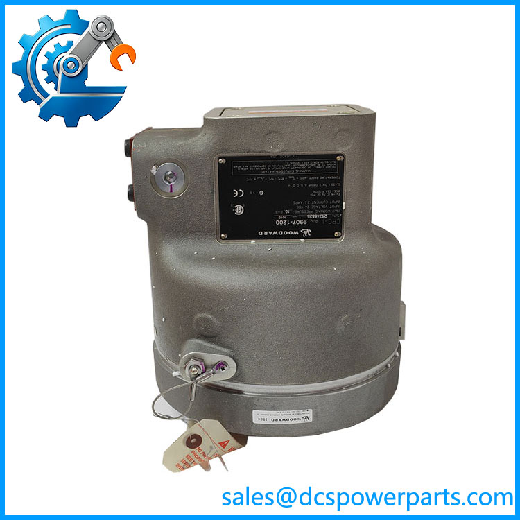
9907-1200
Key Features and Advantages
Closed-loop pressure control at the control port: the unit measures the pressure it is delivering and closes a PID on it, so the controlled variable is the oil pressure the servo actually sees, not a current that is assumed to correspond to one. On a valve whose friction and drain path change with temperature, that is the difference between repeatable positioning across a load swing and a stroke that has to be re-tuned seasonally.
Single moving element in the oil path: a rotary three-way valve with a self-cleaning port design and no nozzle to plug. Turbine oil carries silt, varnish and the occasional water; a converter with one moving part and generous clearances tolerates what a nozzle-flapper device cannot, and the difference shows up as years of service rather than as a specification.
Mechanical fail-safe with no software in the path: an internal return spring ports control pressure to drain whenever the unit is unpowered or has detected a failure. Loss of 24 V, a failed pressure sensor and a hung processor all converge on the same safe outcome, and the mechanism can be proved by de-energising the unit during commissioning — a test worth doing once rather than trusting.
Redundancy at three levels, not one: redundant setpoint inputs voted in the converter, redundant pressure sensors voted in the converter, and two full CPC-II units arranged Master/Slave with automatic transfer and an “In Control” discrete output. A plant can therefore choose the level of redundancy its availability case actually justifies instead of buying a fully redundant skid for a duty that does not need one.
Deliberate setpoint offset in standby: the not-in-control unit of a pair has its setpoint biased so the two valves do not interact. It is a small detail with a large effect on commissioning time, and it is the reason a pair can be brought into service without a day of hunting between two converters.
Eleven-point linearisation: the valve’s flow characteristic can be corrected digitally rather than by de-tuning the whole loop. Sluggish mid-stroke response on a staged inlet valve is usually a linearisation problem, not a tuning problem, and this is the tool that separates the two.
Silt buster for the unit that is not working: a scheduled symmetrical dither, default once a day for 24 ms, keeps the standby converter’s valve from silting while it waits. In a redundant pair the standby unit is the one that fails when it is finally asked to take control, and this routine exists precisely for that failure mode.
Manual stroke, locally and remotely: a manual stroke screw under the front cap and a manual stroke function in the service tool allow the valve to be exercised without a controller command — the practical way to prove the hydraulic path before the control loop is trusted.
Zone 2 certification on a 25 kg hydraulic device: Ex nA IIC T4 Gc and Class I Division 2 Groups A–D at 85 °C ambient. Because it is non-sparking rather than flameproof, the installation requirements are ordinary: no conduit seals, no purge, no special enclosure — as long as the area really is Division 2.
Honest limits: it is not flameproof, so it cannot go into Division 1 (that is 9907-1199); it is not a 25 bar device; it has no LVDT and no fieldbus; and it needs a clean, filtered, pressure-stable oil supply to meet its published dynamics. Those are not shortcomings, they are the terms of use.
Applications
Steam turbine governor valve positioning: the core duty. Single-acting steam valve servos on mechanical-drive and generator-drive turbines, where the converter turns a 4–20 mA demand from the governor into the oil pressure that positions the throttle valve. Speed and load control quality at the turbine is, in the end, valve position quality at this device.
Extraction and admission turbines: machines with more than one controlled valve, where the converter’s linearisation and pressure stability matter most because the valves interact. The 505E and 505XT controls are the usual command source; the CPC-II is the muscle.
Combined cycle and industrial steam plants: turbines driving compressors, fans and generators in paper mills, sugar mills, chemical plants and district heating, where the machine room is hot and the oil is old, and where the silt-tolerant valve and the daily dither do the work that a nozzle would fail at.
Fuel valve positioning: the CPC-II family is specified for steam and/or fuel valves, so gas and liquid fuel valve servos on turbines that use hydraulic actuation fall within its intended use.
Replacement of legacy converters: the standard adapter plate exists to interface the CPC-II with systems designed around Voith I/H converters, and the manual includes a dedicated chapter on replacing older CPCs and non-Woodward converters. For a plant with 1980s-era converters and no spares channel, this is the practical modernisation path — and the reason the 10 bar versus 25 bar and Zone 2 versus Zone 1 distinctions must be settled before the order.
Redundant and high-availability installations: dual-CPC Master/Slave arrangements on machines where a converter failure should not mean a shutdown, and where the transfer must be automatic and annunciated rather than discovered.
Marine and offshore steam plants: the family carries DNV marine certification for the enclosure class, and the ambient range down to −40 °C suits unheated machinery spaces and deck-level installations.
Where it does not fit: Division 1 or Zone 1 areas, which require 9907-1199 or 9907-1349; 25 bar systems, which require 9907-1197 or 9907-1198; double-acting servos without an appropriate interface; and any application expecting an electronic module, an I/O board or a MicroNet component.
Related Products
9907-1199 — hydraulically identical 10 bar unit with Zone 1 / Class I Division 1 certification; the substitute question that decides most orders. 9907-1349 — further 10 bar variant certified for both Zone 1 and Zone 2 service. 9907-1228 — 10 bar, Zone 2 sibling; order-code-level differences from 9907-1200 are not published, so confirm against the application. 9907-1198 — 25 bar supply / 25 bar control version, Zone 2; the higher-pressure member for systems running at 25 bar. 9907-1197 — 25 bar version with Zone 1 and Zone 2 certification. 9907-1253 / 9907-1254 — factory-configured redundant models (10 bar and 25 bar respectively) for dual arrangements. 8918-116 / 8918-118 — CPC-DX dual transfer skid part numbers: two CPCs on one manifold with a transfer valve, for fully redundant installations. 505 / 505E / 505XT — Woodward steam turbine controls that typically supply the 4–20 mA pressure demand and the redundant demand pair. Voith I/H adapter plate — the interface that allows 9907-1200 to replace a Voith converter without re-piping the manifold.
Installation and Maintenance
Before installation: settle the two questions that decide whether the unit is even permissible. Confirm the area classification — 9907-1200 is Zone 2 / Division 2 only, and a Division 1 location needs 9907-1199; and confirm the system pressure — this is the 10 bar supply model, with control pressure 0–10 bar(g) and a recommended maximum setting below 70 % of supply, and a 25 bar system needs a 25 bar unit. Then check the oil: mineral or synthetic per Woodward manual 25071, viscosity 20–100 cSt, filtration 24–40 µm nominal β75, cleanliness ISO 20/16 or better. Flush the supply line, the drain and the line to the servo before the unit is connected — contamination introduced at installation is the most common cause of a converter that underperforms from its first day. Provide an isolation valve upstream of the supply port, and in a redundant pair provide isolation on both supply and control ports so a failed unit can be serviced online.
Installation: mount on the adapter manifold with four M10×1.5 screws engaging at least 16 mm, torqued typically 60–80 N·m for alloy steel socket head cap screws; O-ring face seals must be in place, and the recommended line bore is 18 mm with nothing below 12 mm. Any attitude is acceptable, but fluid ports facing downward is preferred where contamination or entrained water is a concern. Wire S to supply, C to the servo control pressure, T to drain — the ports are marked on the fluid interface. Supply the electronics from 18–32 VDC with a source able to deliver 2 A continuously and 5 A for two seconds, and provide an external means of isolating that supply, since the unit has no input switch of its own. Use the service tool over RS-232 to set range, linearisation and dynamics, then prove the manual stroke and the fail-safe action before the loop is closed.
Maintenance: verify the fail-safe path at every outage by de-energising the unit and confirming control pressure falls to drain; a converter that has seized will otherwise be discovered during a trip. Keep the oil temperature inside 15–70 °C and the ambient below 85 °C at the surface — the published performance assumes it, and a unit mounted next to a steam line is not meeting that assumption. Change the supply filter on schedule, watch internal leakage trends through the service tool rather than by ear, and leave the silt buster enabled on standby units of a redundant pair. Keep one serviceable 9907-1200 per converter type on the shelf: at 25 kg it is a two-person lift, and the lead time is not one a running machine can absorb.
Warranty and Quality
Every 9907-1200 is supplied as a Woodward CPC-II current-to-pressure converter, 10 bar supply / 10 bar control, Zone 2 / Class I Division 2 version, identified against Manual 26615 and Product Specification 03352, with the model number confirmed as the Zone 2 variant rather than the Division 1 9907-1199 and with the pressure class confirmed as 10 bar rather than 25 bar. Units are inspected for housing and cover condition, cover seal and locking clamp integrity, manifold face and O-ring counterbore condition, terminal block and PCB state, and evidence of prior rework or field repair; the hydraulic ports are checked for contamination and the internal return spring function is verified. Where a hydraulic test bench is available the unit is pressurised and exercised through its stroke, the analogue output and discrete outputs are confirmed, and the fail-safe drain behaviour is proven. A 12-month repair, replacement or refund commitment applies. Technical support addresses what this part genuinely raises: why 9907-1200 and 9907-1199 are the same valve with different certificates, why a 10 bar unit cannot serve a 25 bar system, why the control pressure setting should stay below 70 % of supply, why a standby unit of a redundant pair needs the silt buster enabled, and why a sluggish mid-stroke response is usually linearisation rather than tuning.