Description
Technical Specifications
| Parameter | Specification |
|---|---|
| Manufacturer | Yokogawa Electric Corporation |
| Product Model | EC401-50 S3 |
| Product Type | ESB Bus Coupler Module |
| Interface | One-port ESB bus |
| Communication Function | FCU-to-node-unit I/O communication |
| Transmission Speed | 128 Mbps |
| Maximum Transmission Distance | 10 m |
| Maximum Connectable Nodes | Up to 9, depending on the FCS database |
| Current Consumption | 0.5 A |
| Approximate Weight | 0.24 kg |
| Compatible FCU Families | AFV30, AFV40, A2FV50, and A2FV70 variants listed in Yokogawa documentation |
| Installation | Designated FCU slot; slots 7 and 8 for dual-redundant ESB bus |
| Style Requirement for CP471 | S3 or later |
| Explosion Protection | Standard type without explosion protection, as indicated by suffix code -5 |
Specifications are based on Yokogawa’s EC401 general specifications. Confirm the precise hardware revision, host FCU, and installed system version before approving a replacement.
Model identification note: In the documented Yokogawa ordering scheme, EC401 identifies the ESB Bus Coupler Module, -50 denotes the standard type without explosion protection and the basic type, and S3 is the style designation. Yokogawa specifies style S3 or later for use with the CP471 processor.
Product Overview
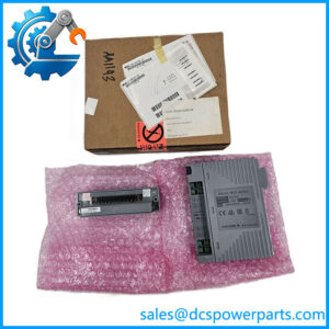
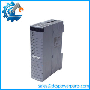
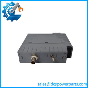
The Yokogawa EC401-50 S3 is an ESB Bus Coupler Module used in compatible Field Control Units within Yokogawa CENTUM control-system architectures. Its purpose is to provide the communication interface between the FCU and connected ESB bus node units. This allows the controller to exchange I/O data with distributed hardware without placing every I/O module directly in the controller chassis.
The EC401 provides a single-port ESB bus interface and supports a documented transmission speed of 128 Mbps for I/O module data. The maximum transmission distance for the specified ESB connection is 10 m, and up to nine node units can be connected, subject to the Field Control Station database and applicable system configuration. These are system-interface specifications, not a guarantee that every FCU can support the maximum node count.
The -50 model designation identifies the standard type without explosion protection and the basic configuration in the documented ordering scheme. The S3 style is particularly important when the module is paired with a CP471 processor: Yokogawa specifies EC401 style S3 or later for that combination. A replacement with an earlier style should not be approved simply because its base model is .
For maintenance teams, the key procurement checks are the full model and style markings, FCU compatibility, required bus topology, and whether the installation uses single or dual-redundant communication. The -50 S3 can be part of a redundant ESB bus arrangement, but redundancy depends on the companion module, designated slots, cabling, and controller configuration. Confirming these details before ordering is essential to avoid installation delays or an unexpected change to the control-system architecture.
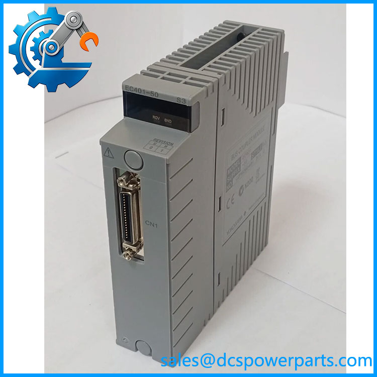
EC401-50 S3
Major Features and Advantages
Dedicated ESB bus interface
The -50 S3 provides the interface between a compatible FCU and ESB bus node units. It is a communication component, not a processor, power supply, or individual signal I/O module. Correct identification of its role helps prevent confusion with SB401 slave interface modules and other bus-interface hardware.
High-speed I/O data transmission
The documented ESB bus transmission speed is 128 Mbps for I/O module data. This supports communication between the control station and its connected node hardware within the specified system architecture. The actual system capacity depends on the FCU model, database, node configuration, and applicable software restrictions.
Support for dual-redundant bus architecture
Yokogawa documents the use of two modules to establish a dual-redundant ESB bus configuration. For the specified FIO FCUs, the modules occupy slots 7 and 8. In a non-redundant arrangement, the is installed in slot 7 and slot 8 must be covered with the specified dummy module. Always confirm the exact FCU installation requirements before removing or relocating hardware.
Compatibility with CP471 processor configurations
The S3 style designation is relevant to processor compatibility. Yokogawa specifies style S3 or later when combining with the CP471 processor module. This is a concrete replacement criterion, particularly for maintenance projects involving controller upgrades or processor replacements. Check the style marking on the actual component tag rather than relying on a supplier’s abbreviated description.
Defined electrical and mechanical characteristics
The module’s documented current consumption is 0.5 A, with an approximate weight of 0.24 kg. These values can help with equipment identification and planning, but they do not establish the functional condition of a particular unit. Connector condition, mounting compatibility, and the installed bus arrangement still require inspection.
Practical replacement planning
For an existing system, a correctly matched can preserve the intended ESB communication architecture without replacing unrelated I/O hardware. That benefit depends on verifying the complete model, style, controller compatibility, and bus configuration. A similar-looking module or an earlier style code should not be assumed interchangeable without documented approval.
Applications
The Yokogawa -50 S3 is used in compatible distributed control systems where an FCU communicates with ESB bus node units. In a process plant, these nodes provide the connection point for distributed I/O modules that collect field measurements and deliver control outputs. The supplies the communication link between the controller and this node infrastructure.
For maintenance and fault recovery, the module may be held as a spare for an established FIO control station. If node communication is lost, engineers should check the diagnostics, bus cable, node-unit status, connector seating, and controller configuration before concluding that the coupler has failed. Replacing the module without checking the rest of the communication path may not resolve the fault.
In redundant installations, the can be used as part of a dual-redundant ESB bus arrangement. The maintenance plan should identify the designated module slots, companion coupler, bus wiring, and expected switchover behavior. Redundancy is a property of the configured system, not a standalone feature that guarantees uninterrupted operation under every failure condition.
The module is also relevant during FCU processor upgrades. If the system is being migrated to a CP471 processor, the style must meet Yokogawa’s S3-or-later requirement. Processor replacement may also require compatible software versions and an approved upgrade procedure, so the coupler should be assessed as part of the complete controller configuration rather than in isolation.
For spare-parts inventory, record the complete -50 S3 designation, installed FCU model, style marking, slot assignment, and redundancy arrangement. This gives procurement and maintenance teams the information needed to assess compatibility before dispatch and helps reduce the risk of installing an unsuitable bus interface.
Related Products
| Model | Relationship |
|---|---|
| -10 S2 | Related variant; style and suffix differences require verification |
| S3 | Same model and style designation |
| EC402 | Related ESB Bus Coupler model with a different interface arrangement |
| SB401 | ESB bus interface slave module used in compatible node units |
| Processor module for which style S3 or later is specified | |
| AFV30S / AFV30D | Compatible FCU family listed in documentation |
| AFV40S / AFV40D | Compatible FCU family listed in documentation |
| A2FV50S / A2FV50D | Compatible FCU family listed in documentation |
| A2FV70S / A2FV70D | Compatible FCU family listed in documentation |
| ANB10S / ANB10D | ESB bus node units |
These products are related by system architecture or communication function; they are not all direct substitutes.
Installation and Maintenance
Before installing S3, verify the complete component tag, including model, suffix, and style. Confirm that the host FCU is supported by the applicable documentation and check whether the station uses a single or dual-redundant ESB bus. If a processor is installed or planned, confirm that the coupler meets the S3-or-later style requirement.
Follow the site’s approved isolation and maintenance procedures before removing the module or disturbing bus connections. Record the existing slot assignment and cable routing. For the documented FCU arrangement, a non-redundant is installed in slot 7, with slot 8 covered by the required dummy module. Dual-redundant arrangements use modules in both designated slots. Confirm the instructions for the actual FCU before proceeding.
Inspect the module connector, mounting interface, and ESB cable for physical damage or contamination. Check that the cable and connection arrangement are appropriate for the installed bus system. Avoid modifying connectors or substituting cables based solely on physical fit.
After installation, follow the approved recovery procedure and verify that the FCU recognizes the coupler, expected node units are communicating, and relevant diagnostics have returned to the required state. In redundant configurations, perform the prescribed checks of the companion module and switchover behavior. Do not force a switchover or disturb active control hardware without authorization.
Record the installed part number, style, slot, test results, and any configuration changes in the maintenance history. If communication problems persist, investigate the bus path and connected hardware rather than assuming the replacement module is defective.
Product Assurance
For the Yoko S3, procurement assurance should start with exact identification and documented compatibility. Request clear photographs of the component tag, style marking, connectors, and overall condition. Compare the markings with the removed unit and the FCU hardware records before accepting it as a replacement.
The ‘s published bus specifications describe the product family; they do not prove that an individual unit has passed functional testing. The actual unit’s condition, storage history, and test status should be stated separately. If a seller offers functional testing, request a record of what was tested, the test environment, and the results.
For critical control-system spares, confirm warranty terms, return conditions, packaging, and expected delivery lead time before purchase. If an alternative suffix or style is proposed, require compatibility confirmation rather than relying on a similar product description.
Final acceptance should be based on the complete model and style, FCU compatibility, installation requirements, physical condition, and available test evidence. These checks are especially important when the is part of a redundant bus architecture or a controller upgrade involving the processor.