Description
Technical Specifications
| Parameter | Specification |
|---|---|
| Product Model | AMM42 |
| Manufacturer | Yokogawa |
| Product Function | Two-wire transmitter input multiplexing |
| Documented Related Model | AMM42T |
| Input Signal | 4–20 mA DC |
| Input Capacity | Up to 16 transmitter signals for AMM42T |
| Transmitter Power Supply | 23.5–24.5 V DC for AMM42T |
| Transmitter Supply Output Limit | 60 mA or less for AMM42T |
| Isolation | Yokogawa documentation states the AMM42T input/output signals are not isolated between system and field or between channels |
| Mounting / System | Legacy Yokogawa DCS I/O architecture; exact rack and interface require confirmation |
| Operating Temperature | Confirm against the exact model and suffix |
| Communication Interface | No independent communications interface confirmed for the base model |
| Dimensions and Weight | Confirm against the unit label and applicable general specification |
The table deliberately separates confirmed AMM42T information from details that require model-specific verification. Do not use specifications for a different suffix or a modern replacement module as a substitute for the original hardware documentation.
Product Overview
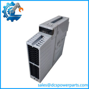
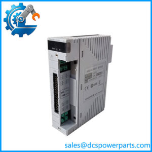
The Yokogawa AMM42 is associated with analog signal acquisition in legacy process-control installations. Its documented AMM42T counterpart is a two-wire transmitter input multiplexer designed to receive multiple 4–20 mA DC signals. This signal format is widely used by process transmitters measuring variables such as pressure, flow, level, and temperature through a suitable transmitter. The module’s role is to interface these current signals with the host control system; the measurement range, engineering units, alarm thresholds, and control response are determined by the field instruments and the configured control application.
A key procurement issue is the difference between the shorter AMM42 designation and the documented AMM42T model. Yokogawa’s technical material identifies the latter explicitly and specifies a capacity of up to 16 transmitter inputs. The same documentation gives a transmitter supply range of 23.5–24.5 V DC, with an output limit of 60 mA or less. These figures are useful when checking the relevant AMM42T installation, but they should not be assumed to apply to an unverified suffix or variant.
Compatibility deserves particular attention in older DCS installations. A module can share a family name with another product and still differ in its connector, terminal arrangement, supply requirements, or system interface. Before replacing an installed AMM42, compare the full nameplate, suffix, I/O nest or mounting arrangement, field wiring, and applicable system documentation. If the part is being sourced for a running plant, confirm the proposed replacement against the approved spare-parts list rather than relying on a general catalog description.
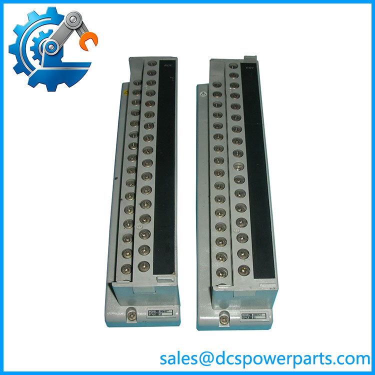
AMM42
Major Features and Advantages
1. Interface for 4–20 mA transmitter signals
The documented AMM42T accepts 4–20 mA DC signals from two-wire transmitters. This provides a defined interface for compatible process instrumentation and allows the control system to use acquired measurements for monitoring, alarms, trending, and control logic. The field transmitter’s own signal range and calibration must still match the configured control-system input.
2. Multi-channel signal handling
Yokogawa documentation specifies up to 16 transmitter signals for the AMM42T. Consolidating multiple signals in a single module can help maintain an organized legacy I/O installation and reduce the number of individual module positions required for the supported configuration. Confirm the actual channel capacity of the unit being purchased before using this figure in a cabinet layout or spare-parts calculation.
3. Transmitter supply considerations
The documented AMM42T provides a transmitter power supply in the range of 23.5–24.5 V DC, with an output limit of 60 mA or less. This information is important when checking the connected transmitter load and troubleshooting a loop that does not produce the expected current. The total load, wiring resistance, and the individual transmitter’s minimum operating voltage must be evaluated as part of the complete loop design.
4. Important isolation limitation
Yokogawa’s documentation states that AMM42T input/output signals are not isolated between the system and field, or between channels. Engineers should therefore assess grounding, common-mode voltage, field wiring, and potential interference using the relevant installation documentation. Do not treat the module as a galvanically isolated input device unless the exact hardware documentation confirms that capability.
5. Legacy-system maintenance
The AMM42 is relevant to maintenance planning for existing Yokogawa installations that continue to use this generation of I/O hardware. Keeping a verified spare can reduce the time required to respond to a module fault, but the spare must match the actual installed variant. Physical fit alone is insufficient evidence of electrical or system compatibility.
6. Replacement-path assessment
For projects modernizing older I/O, Yokogawa documentation identifies the AAI143-HM family in the context of an RIO system upgrade for AMM42T. This is a useful lead for an upgrade assessment, not proof that an AAI143-HM is a direct, plug-compatible replacement for every AMM42 installation. Terminal interfaces, wiring conversion, system configuration, and the scope of the upgrade must be checked.
Typical Applications
-
Process transmitter acquisition: Receiving 4–20 mA signals from compatible two-wire transmitters for use by a DCS.
-
Pressure monitoring: Acquiring current signals from pressure transmitters for process indication, alarm handling, and control logic.
-
Flow measurement: Bringing compatible transmitter outputs into the control system for flow monitoring and process calculations.
-
Level measurement: Collecting current signals from suitable level transmitters for tank, vessel, and process-level monitoring.
-
Temperature measurement: Acquiring 4–20 mA outputs from temperature transmitters. The module receives the current signal; it is not itself a direct thermocouple or RTD input unless the exact documentation specifies otherwise.
-
Legacy DCS support: Maintaining existing control cabinets where the installed module, wiring, and system configuration are verified as compatible.
-
I/O upgrade planning: Evaluating the transition from older transmitter input hardware to a supported replacement architecture, including interface and wiring changes.
These examples describe possible uses of the documented 4–20 mA input function. They do not establish compatibility with every transmitter, DCS generation, or safety-related application.
Related Products
Related Yokogawa models for reference. Similarity of function does not establish direct interchangeability.
| Model | Relationship |
|---|---|
| AMM42T | Documented two-wire transmitter input multiplexer; the closest specification reference for the AMM42 designation. |
| AMM52T | Corresponding two-wire transmitter output multiplexer for 4–20 mA signals; a different function. |
| AAI143-HM | 16-channel, isolated 4–20 mA analog input module associated with the RIO system upgrade for AMM42T. |
| AAI143 | Yokogawa 16-channel isolated analog input module for 4–20 mA signals; verify the suffix and intended system. |
| AAI543 | Yokogawa 16-channel isolated analog output module for 4–20 mA signals; an output module, not an AMM42 substitute. |
The model relationships above are based on Yokogawa documentation for transmitter multiplexers and I/O upgrade hardware. Confirm the exact hardware revision and approved configuration before selecting any alternative.
Installation and Maintenance
Before installing or replacing a Yokogawa AMM42, record the complete model designation and inspect the unit’s nameplate. If the label identifies AMM42T or includes an additional suffix, use the documentation for that exact variant. Check the mounting position, interface hardware, connector type, wiring diagram, and host-system requirements before removing the existing module.
-
Apply site isolation procedures. Follow approved lockout/tagout and control-system maintenance procedures. Do not remove or insert the module under power unless the applicable system documentation explicitly permits it.
-
Verify the signal type. Confirm that connected instruments provide the required 4–20 mA DC signal and that the wiring matches the module’s terminal or cable arrangement.
-
Check the transmitter supply. For the documented AMM42T configuration, verify the specified 23.5–24.5 V DC supply range and the 60 mA output limit. Do not apply these values to a different variant without confirmation.
-
Review grounding and isolation. Since the AMM42T documentation specifies no isolation between field and system or between channels, check the grounding and signal-common arrangement carefully.
-
Inspect connections. Examine connectors, terminals, cables, and nearby wiring for looseness, corrosion, contamination, or insulation damage.
-
Commission systematically. Test representative input loops with an approved procedure and confirm that the expected process value reaches the host system. Check channel mapping, scaling, alarms, and control logic.
-
Record the result. Document the replacement model, revision, loop tests, and any configuration changes in the site’s maintenance records.
If an input reading is incorrect, investigate the transmitter, loop power, wiring, grounding, configuration, and host-system channel assignment before concluding that the module has failed.
Product Assurance and Procurement Checks
For a AMM42 procurement request, the most important assurance step is to confirm the exact hardware identity. Available documentation is clearer for AMM42T than for the shorter designation, so a seller’s generic description should not replace a nameplate check or manufacturer specification.
Before approving a unit, request confirmation of the full model and suffix, physical condition, included interface components, and any available functional test results. For used or refurbished stock, establish what was tested and whether the test covered the actual input channels and interfaces needed by the installation. A visual inspection alone does not prove functional performance.
For planned replacements or upgrades, confirm the system generation, rack or I/O interface, wiring arrangement, and approved migration path with the site’s control-system documentation. Do not assume that the AAI143-HM or another analog input module can be installed directly in place of an AMM42 without any wiring or configuration changes.
Procurement recommendation: The AMM42 is associated with Yokogawa legacy transmitter-input multiplexing, but verify whether the required part is specifically AMM42T before relying on its 16-channel capacity and electrical specifications.