Description
Technical Specifications
| Parameter | Specification |
|---|---|
| Product Model | ADV551-P00 |
| Manufacturer | Yokogawa |
| Product Type | Digital output module |
| Number of Channels | 32 |
| Rated Applied Voltage | 24 V DC |
| External Supply Voltage Range | 20.4–26.4 V DC |
| Output Format | Current sink |
| Maximum Load Current | 100 mA/channel at 26.4 V DC |
| Maximum Output ON Voltage | 2 V DC |
| Maximum OFF-State Leakage Current | 0.1 mA |
| Isolation: Output to System | 2 kV AC for 1 minute |
| Isolation Between Commons | 500 V AC for 1 minute; common grouping by 16 channels |
| Output Response Time | Up to 3 ms for status output; up to 10 ms for mixed status and pulse outputs |
| Pulse-Width Function | Supported |
| Time-Proportional Output | Supported |
| Approximate Module Weight | 0.2–0.3 kg, depending on source/configuration |
Specifications are drawn from Yokogawa documentation and corroborating product data. Verify the applicable manual revision and the exact hardware suffix before engineering approval.
Product Overview
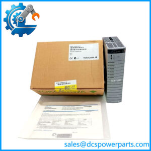
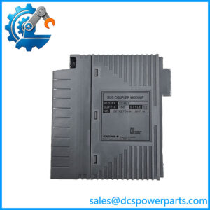
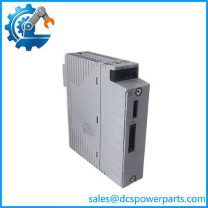
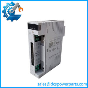
The Yokogawa ADV551-P00 is designed for discrete output duties in industrial control systems using compatible Yokogawa field I/O hardware. With 32 isolated 24 V DC output channels, it allows a controller to issue multiple field commands from a single module position. Typical loads may include interface relays, solenoid-valve circuits, pilot devices, and indicator lamps, provided their voltage, current, and electrical characteristics remain within the module’s rated limits.
The module uses a current-sink output format, so the field wiring must match the output circuit’s polarity and supply arrangement. The published maximum load current is 100 mA per channel at 26.4 V DC. That rating should not be interpreted as permission to drive any load with a nominal 24 V label: inrush current, inductive energy, common grouping, external supply protection, and the field device’s actual input circuit all matter. Loads that exceed the output rating require a suitable interposing device rather than direct connection.
The -P suffix identifies pulse-width output and time-proportional output capability. These functions can be useful where the control strategy requires timed switching rather than only a steady ON/OFF state. They do not make the module an analog output device; it still switches discrete 24 V DC circuits. The 00 portion denotes the basic type in the published suffix scheme, but does not independently confirm the module’s condition, revision, or complete installed configuration.
For procurement, match the complete model code and any installed option code, then verify the required terminal block or cable interface. The module itself should not be treated as a complete field wiring assembly when the original installation also uses separate connection accessories.
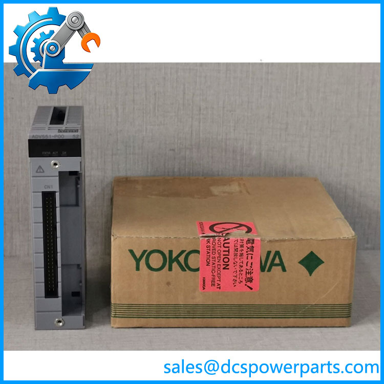
ADV551-P00
Major Features and Advantages
32-channel output density
The ADV551-P00 consolidates 32 discrete output points into one module. This can reduce the number of module positions needed for a panel or control cabinet, while allowing multiple field commands to be organized within a consistent I/O arrangement. Channel density alone, however, does not determine cabinet capacity: terminal assemblies, wiring ducts, power distribution, and maintenance access must also be considered.
Pulse-width and time-proportional control
The -P configuration supports pulse-width and time-proportional output functions. These functions can support timed switching sequences and control strategies that repeatedly energize and de-energize a discrete load. Engineers should verify the intended point mode, configured timing range, and application behavior in the applicable Yokogawa engineering documentation before commissioning.
Defined electrical operating limits
The published maximum ON-state voltage drop is 2 V DC, and the maximum OFF-state leakage current is 0.1 mA. These values help engineers evaluate voltage available to a connected load and determine whether an OFF-state circuit could affect a sensitive field device. The actual circuit must still be checked against the device manufacturer’s minimum operating voltage and leakage-current tolerance.
Isolation and channel organization
The specified isolation is 2 kV AC for one minute between output signals and the system, and 500 V AC for one minute between commons. The common arrangement is grouped by 16 channels. This separation supports defined electrical boundaries, but it should not be mistaken for protection against every field fault. Correct grounding, supply protection, cable routing, and wiring practices remain necessary.
Integration within a compatible Yokogawa I/O system
The ADV551 family is documented for Yokogawa field I/O applications. The correct connection accessories depend on the installation: the published options include a KS cable interface adapter and pressure-clamp terminal arrangements. Confirm which accessories are already installed rather than assuming the module is supplied with every terminal or cable component.
Applications
Distributed control system output points
The ADV551-P00 can serve as the discrete output interface between a compatible Yokogawa control system and field devices. In process plants, output points commonly operate interface relays, signal lamps, and other devices that accept a suitable 24 V DC switching signal. The engineering team must confirm each load’s current demand, wiring polarity, and required isolation before connecting it directly.
Solenoid valves and auxiliary relays
Solenoid-valve circuits and relay coils are possible applications when their electrical characteristics fall within the module’s limits. Inductive loads need particular attention because switching them can produce voltage transients. Confirm whether external suppression is required and approved for the specific load and control design. Do not assume the module alone provides all the protection required by an inductive field circuit.
Timed and repetitive switching
The pulse-width and time-proportional functions can be useful for applications where the controller must generate timed output patterns. Depending on the control design, these may be used for repetitive switching or time-based actuation. The module is not a substitute for a dedicated analog output where a continuously variable current or voltage signal is required.
Control panels and packaged equipment
A 32-channel module can support packaged skids, auxiliary equipment, and plant control panels that need numerous discrete output points. Before deploying it in a new panel, check the approved I/O architecture, the field supply arrangement, common grouping, terminal assembly, and required diagnostics. The model’s existence within the ADV551 family does not establish compatibility with every Yokogawa controller or every software revision.
Maintenance and replacement projects
For an existing installation, the -P00 may be considered when the removed module has the same complete ordering code and the system documentation confirms compatibility. A physically similar module or one from the same family is not automatically interchangeable. Confirm the configured point modes, wiring accessories, and any site-specific qualification requirements before returning the control loop to service.
Related Products
The following are related models or connection accessories in the same Yokogawa digital I/O product family. Their inclusion indicates a product-family relationship, not guaranteed interchangeability.
| Model | Relationship |
|---|---|
| Base 32-channel, 24 V DC isolated digital output module family | |
| ADV561 | 64-channel, 24 V DC isolated digital output module |
| ADV151 | 32-channel, 24 V DC isolated digital input module |
| ADV161 | 64-channel, 24 V DC isolated digital input module |
| ATD5S-00 | Pressure-clamp terminal block accessory for digital output |
| ATD5A-00 | KS cable interface adapter for 32-channel digital I/O |
| ATD5D-00 | Dual pressure-clamp terminal block option for applicable digital output configurations |
| ACCC01 | Connector cover accessory for MIL cable connections |
Confirm accessory availability and the applicable connection scheme against the installed hardware.
Installation and Maintenance
Before installing a -P00 replacement, isolate the relevant field power and follow the plant’s approved electrical safety and lockout procedures. Verify the module designation and inspect the existing assembly for signs of overheating, contamination, damaged contacts, or mechanical stress. Do not insert or remove the module under power unless the specific system documentation explicitly permits that procedure.
Check the field supply before connecting the loads. The documented external supply range is 20.4–26.4 V DC. Confirm polarity and ensure that each output’s load current remains within its rating. Because the output is current-sink type, verify the complete circuit topology rather than relying only on the nominal voltage of the connected device. Review the common grouping and protective devices as part of the wiring check.
Confirm the terminal block, cable adapter, and connector arrangement used in the cabinet. A module-only replacement may require reuse or separate procurement of the correct interface hardware. Never force a connector or modify wiring solely to accommodate a physically similar part.
After installation, verify module recognition and configuration in the control system. Test each affected output under an approved commissioning procedure, including normal ON/OFF switching and any pulse-width or time-proportional behavior used by the application. Check field-device response and alarm handling before returning the loop to normal service. Record the installed model code, revision or hardware identifiers, test results, and any wiring changes in the maintenance record.
Product Assurance
For procurement of theawa , the essential checks are identity, configuration, physical condition, and evidence of functional testing. The model designation identifies a 32-channel isolated digital output module with pulse-width and time-proportional output capability; it does not establish the condition or service history of an individual unit.
Before dispatch, request confirmation of the full nameplate model, available revision information, included accessories, and any visible signs of repair or damage. If functional testing is offered, ask which test points were checked and whether the results are documented. A visual inspection alone cannot demonstrate that all 32 channels switch correctly or that pulse-output functions operate as required.
For a replacement intended for an operating plant, compatibility should be checked against the site’s bill of materials, installed I/O hardware, connection accessories, and control-system configuration. Any required warranty, test report, or traceability documentation should be agreed upon before purchase. Availability, delivery time, and supplied condition must be confirmed for the actual unit being quoted rather than inferred from the model number.
The objective is a verifiable replacement decision: a correctly identified module, an appropriate connection arrangement, and acceptance criteria that match the plant’s maintenance and commissioning requirements.