Description
Technical Specifications
| Parameter | Specification |
|---|---|
| Manufacturer | Yokogawa |
| Product Model | ADV551-P00 S2 |
| Product Type | Isolated digital output module |
| Number of Channels | 32 |
| Rated Output Voltage | 24 V DC |
| External Supply Rating | 24 V DC, 50 mA |
| External Supply Voltage Range | 20.4–26.4 V DC |
| Output Format | Current sink |
| Maximum Load Current | 100 mA per channel at 26.4 V |
| Maximum ON-State Voltage Drop | 2 V DC |
| Maximum OFF-State Leakage | 0.1 mA |
| Output-to-System Withstand Voltage | 2 kV AC for 1 minute |
| Common-to-Common Withstand Voltage | 500 V AC for 1 minute, between 16-channel common groups |
| Output Functions | ON/OFF status, pulse-width output, time-proportional output |
| Status Output Response | 3 ms or less |
| Mixed Status/Pulse Response | 10 ms or less |
| Maximum Current Consumption | Approximately 700 mA at 5 V DC; 60 mA from external supply |
| Approximate Weight | 0.2–0.23 kg |
Specifications are based on Yokogawa’s ADV551 documentation and corroborating model-specific listings. Actual ratings and accessories should be checked against the applicable hardware revision and product nameplate.
Suffix note: Yokogawa documentation identifies -P as the pulse-width/time-proportional output option. The 00 suffix codes indicate the basic type without a status display or explosion protection in the documented ordering scheme. The additional S2 designation appears in supplier listings, but its exact meaning should be confirmed from the unit label and applicable manufacturer documentation rather than treated as a separate functional specification.
Product Overview
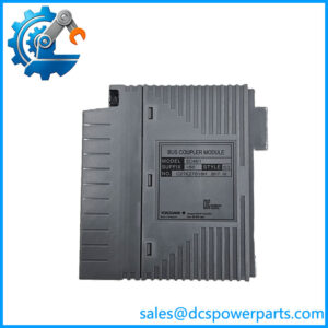
The Yokogawa ADV551-P00 S2 is a 32-channel digital output module intended to transfer discrete control commands from a compatible process control system to field devices. Its 24 V DC current-sink outputs can be used for suitable interface circuits and loads, including relay interfaces, indicator circuits, and selected solenoid-actuation circuits. Each application must remain within the specified channel-current limit and the electrical requirements of the connected device. This module is not a universal replacement for relay output cards, sourcing outputs, or analog output modules.
The -P model option adds pulse-width output and time-proportional output functions alongside standard ON/OFF status control. These functions can be useful where a control strategy requires timed digital pulses or proportional control implemented through switching. Response time depends on the selected output mode: Yokogawa documentation gives a maximum of 3 ms for status output and 10 ms for mixed status and pulse output. Pulse-width settings and the controlled device’s response requirements should be checked in the system configuration before commissioning.
The module is documented as supporting dual-redundant configurations in compatible systems. Redundancy, however, depends on the controller, I/O node, terminal arrangement, wiring, and configuration—not simply on installing two modules. For a replacement project, verify the complete part number, suffixes, terminal block or cable interface, and existing control-system compatibility. The S2 marking should also be matched against the installed unit’s identification before treating a candidate replacement as equivalent.
For maintenance teams, the important purchasing question is whether the offered unit matches the installed hardware and required output behavior. A visually similar ADV551 variant may have a different suffix, display option, environmental qualification, or connection arrangement. Confirming these details before shipment helps avoid installation delays and unplanned control-system changes.
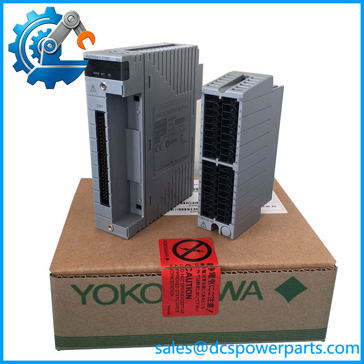
ADV551-P00 S2
Major Features and Advantages
32 discrete output channels
The ADV551-P00 S2 provides 32 digital output channels in one module, allowing a compatible control-system node to command multiple discrete field devices. The channel count can reduce the number of separate modules required, provided the installed node, terminal hardware, and control configuration support the arrangement.
Pulse-width and time-proportional control
The -P option supports pulse-width and time-proportional output functions. These can support applications that use timed switching commands rather than simple steady-state ON/OFF signals. The intended pulse range, timing resolution, and response requirements must be checked against the applicable Yokogawa manual and control application before implementation.
Defined electrical limits
The published maximum load current is 100 mA per channel at 26.4 V DC. The maximum ON-state voltage drop is 2 V DC, while the maximum OFF-state leakage is 0.1 mA. These figures matter when checking relay pickup requirements, input thresholds, and whether an interface device will reliably recognize the commanded state. Loads exceeding the rated current require a suitable external interface; do not assume the module can directly drive them.
Isolation and redundancy support
Yokogawa specifies 2 kV AC withstand voltage between output signals and the system for one minute, and 500 V AC between common groups for one minute under the documented arrangement. These are withstand-test ratings, not operating-voltage ratings. The manufacturer also documents support for dual-redundant operation in compatible configurations. Neither isolation nor redundancy removes the need for correct grounding, wiring, and installation practices.
Practical replacement considerations
The primary advantage during maintenance is retaining the intended 32-channel output architecture and pulse-related functionality without redesigning the control application. That benefit depends on matching the actual suffix, connection accessories, and system revision. A substitute should not be approved solely because its front label says ADV551.
Applications
The Yokogawa -P00 S2 is intended for discrete output duties in compatible industrial process-control systems. Typical applications include issuing ON/OFF commands to field interface relays, switching suitable indicator circuits, and controlling compatible solenoid or actuator interface circuits. The field device’s rated voltage, input characteristics, inrush current, and required switching frequency must be reviewed before connecting it to an output channel.
In process plants, digital output modules often form the final electrical link between a controller’s logic and equipment in the field. For example, a control strategy may issue a command to open or close a valve through an appropriately rated interface circuit. The module provides the discrete command; it does not independently verify that the valve has reached its requested position. Position feedback and other confirmation signals must be handled through the appropriate input channels and control logic.
The pulse-width and time-proportional functions may be useful in applications where a device responds to timed switching signals. Suitability depends on the controlled equipment, the configured pulse timing, and the requirements of the process. Do not assume that a pulse-capable output is suitable for every motor, heater, or proportional actuator; verify the device manufacturer’s switching limits and use a suitable power interface where required.
For systems configured with redundant output hardware, the can be considered where the existing Yokogawa architecture explicitly supports that arrangement. The engineering team should confirm the controller and node configuration, module pairing, field wiring, and required behavior during a module fault or switchover. A redundant installation should be validated against the project’s control and availability requirements.
The module may also be relevant to maintenance stock planning when an existing installation uses the same model and suffix configuration. Before holding it as a critical spare, document the installed part number, connection hardware, configured output mode, and any environmental or hazardous-area requirements. This helps prevent a spare with the correct base model but the wrong configuration from delaying a repair.
Related Products
These Yokogawa models and accessories are related by digital I/O function or connection requirements. They are not all direct substitutes.
| Model | Relationship |
|---|---|
| Base 32-channel digital output module family | |
| ADV561 | 64-channel digital output module; different channel count |
| ADV151 | 32-channel digital input module |
| ADV161 | 64-channel digital input module |
| ATD5S-00 | Pressure-clamp terminal block option listed for compatible 32-channel digital outputs |
| ATD5S-10 | Pressure-clamp terminal block option with surge absorber |
| ATD5D-00 | Dual pressure-clamp terminal block option |
| ATD5D-10 | Dual pressure-clamp terminal block option with surge absorber |
| ATD5A-00 | KS cable interface adapter for compatible 32-channel digital I/O |
| AKB331 | Dedicated cable listed for compatible I/O connections |
Confirm each accessory’s applicability to the installed hardware and cable arrangement before purchase.
Installation and Maintenance
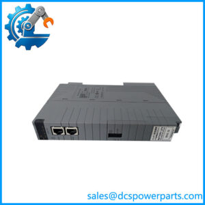
Before installing the -P00 S2, record the full model designation and inspect the existing module label. Confirm that the replacement matches the installed output module’s suffix, hardware revision requirements, I/O node, and connection method. Check whether the installation uses a pressure-clamp terminal block, a cable interface adapter, or another documented connection arrangement.
Follow the site’s approved isolation and lockout procedures before handling the module or its field wiring. Verify the external 24 V DC supply, polarity, grounding, and load ratings. Because the output format is current sink, confirm that the field circuit is wired for that output type; do not assume it can replace a sourcing-output module without changes to the circuit design.
Inspect connectors, terminal blocks, and field conductors for looseness, corrosion, heat damage, or incorrect labeling. Confirm that each connected load remains within the 100 mA per-channel rating at the specified conditions. For DC relay coils, use appropriate suppression components as required by the relay and circuit design. Suppression and interface components must be selected for the actual load and switching requirements.
After installation, verify channel assignments and test representative outputs using an approved commissioning procedure. Check standard ON/OFF response, pulse-width behavior, and time-proportional output where those functions are used. Confirm the state of connected equipment through feedback signals rather than relying solely on the output command. If redundancy is configured, perform the required redundancy and switchover checks under the site’s approved test plan.
Do not change output forcing, pulse parameters, or redundant-module settings without authorization. Record the replacement model, revision, wiring changes, configuration adjustments, and test results in the maintenance history. Consult the applicable Yokogawa documentation for installation restrictions and any requirements specific to the control-system version.
Product Assurance
For a replacement -P00 S2, procurement assurance should begin with part-number and configuration verification. Request clear photographs of the nameplate, suffix markings, connectors, and overall module condition. Compare the supplied identification against the removed unit and the site’s approved spare-parts record. Where S2 appears as an additional designation, verify its significance from the actual label and applicable documentation.
A responsible supply process should distinguish confirmed technical specifications from details that remain unverified. The published 32-channel count, 24 V DC rating, current-sink output type, and -P pulse-related functions can guide the initial review. They do not, by themselves, establish the offered unit’s service history, remaining life, firmware or hardware revision, or suitability for a specific installed node.
Before shipment, agree on the unit’s actual condition, inspection scope, available test evidence, warranty terms, and delivery lead time. If functional testing is offered, ask which tests were performed, whether the module was powered, which output functions were exercised, and whether the results are documented. Do not treat a visual inspection as proof of full functional performance.
For critical process equipment, release the replacement only after the responsible controls engineer confirms compatibility with the installed system and its field wiring. These checks help reduce the risk of receiving a correctly labeled but incorrectly configured or unsuitable spare.