Description
Technical Specifications
| Parameter | Specification |
|---|---|
| Product Model | AAI143-S00 S1 — verify complete nameplate |
| Manufacturer | Yokogawa Electric Corporation |
| Product Type | Analog input module |
| Input Channels | 16, isolated |
| Input Signal | 4–20 mA DC |
| Maximum Allowable Input Current | 24 mA |
| Input Resistance, Power On | 270 Ω at 20 mA to 350 Ω at 4 mA |
| Input Resistance, Power Off | 500 kΩ or greater |
| Published Accuracy | ±16 µA |
| Data Update Period | 10 ms |
| Input-to-System Withstand Voltage | 1,500 V AC for 1 minute, subject to connection configuration |
| Transmitter Supply | At least 19.0 V at 20 mA; no more than 25.5 V at 0 mA |
| Transmitter Supply Current Limit | 25 mA |
| Maximum Current Consumption | 230 mA at 5 V DC; 540 mA at 24 V DC |
| Approximate Weight | 0.3 kg |
| Connection Options | Pressure-clamp terminal, MIL connector cable, or dedicated KS1 cable |
| HART Communication | Not indicated for the standard -S model; verify the exact variant |
Specifications are based on Yokogawa’s published AAI143 data. Actual isolation performance may depend on the cable and connection hardware used.
Product Overview
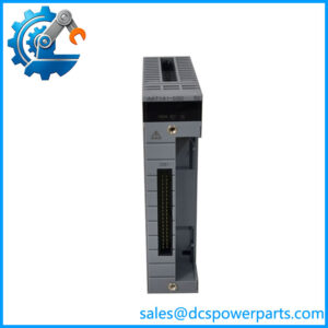
The Yokogawa AAI143-S00 S1 is associated with the AAI143 family of isolated analog input modules used to collect process signals in compatible distributed control systems. It accepts 4–20 mA DC signals across 16 isolated input channels, converting field measurements into data that the control system can use for monitoring, alarms, trending, and regulatory control. Typical measurement sources include pressure, flow, level, and temperature transmitters with a suitable current output.
The module supports channel-by-channel configuration for 2-wire or 4-wire transmitter connections. Its transmitter supply specification is at least 19.0 V at a 20 mA load, with a maximum of 25.5 V at zero current and a 25 mA output current limit. When engineering a loop, account for the transmitter’s minimum operating voltage, cable resistance, barriers, isolators, and other series devices. A loop that works on a bench may fail in the field if the available voltage margin is insufficient.
The published data update period is 10 ms, with stated accuracy of ±16 µA. These figures are useful when assessing measurement requirements, but they should not be confused with total installed-loop accuracy. Transmitter performance, wiring, calibration, environmental conditions, and the control system’s configuration also affect the final measurement. The standard -S version should not be assumed to provide HART communication; Yokogawa documents a separate -H suffix for the HART-capable variant.
For procurement, the key issue is the complete ordering identity. The standard published code is AAI143-S00, while S1 appears in some supplier descriptions as an additional designation. Confirm whether it represents a revision, stock identifier, or another ordering detail on the actual unit before approving a replacement.
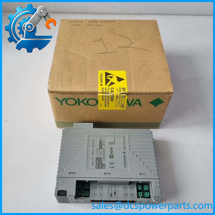
AAI143-S00 S1
Major Features and Advantages
Sixteen isolated current-input channels
The AAI143-S00 S1 designation is associated with a 16-channel isolated 4–20 mA input module. This channel density supports multiple process measurements in one I/O module position. Isolation helps establish electrical separation between the input side and the system, subject to the specified connection arrangement and installation conditions.
Defined input resistance and current limits
The module’s published powered input resistance varies from approximately 270 Ω at 20 mA to 350 Ω at 4 mA. Its maximum allowable input current is 24 mA. These values matter when evaluating loop loading, transmitter compatibility, and behavior under abnormal signal conditions. Engineers should check the complete loop budget rather than considering the input current range alone.
Support for 2-wire and 4-wire transmitters
Channel-level configuration supports 2-wire and 4-wire transmitter arrangements. This provides flexibility when integrating field instruments with different power requirements. Before wiring, verify the transmitter type, polarity, supply arrangement, and channel setting against the actual installation drawings.
Fast data refresh for process monitoring
The specified 10 ms update period supports regular acquisition of process measurements. Whether this rate is sufficient depends on the process dynamics, controller scan configuration, alarm requirements, and overall loop design. The update specification should not be interpreted as a guarantee of end-to-end control-loop response time.
Compatibility with established Yokogawa FIO hardware
The family is documented for compatible Yokogawa FIO installations, with supported signal connection options including pressure-clamp terminals, MIL connector cables, and dedicated cables. The appropriate interface depends on the installed terminal board and cable assembly. A replacement should be checked against the system bill of materials rather than selected by model-family resemblance alone.
Applications
Pressure and differential-pressure measurement
Compatible pressure transmitters can provide 4–20 mA signals to the module for monitoring vessel pressure, line pressure, or filter differential pressure. Engineers should verify transmitter range, scaling, loop power, and alarm limits in the control configuration before returning the measurement to service.
Flow and level monitoring
Flowmeters and level transmitters with 4–20 mA outputs are common sources for isolated analog inputs. The module acquires the current signal; engineering software and the controller configuration determine how it is scaled into engineering units. Check the configured lower and upper range values when replacing the hardware to avoid incorrect readings or alarm thresholds.
Temperature measurement through transmitters
Where temperature sensors are connected to a field transmitter that produces a 4–20 mA signal, the can receive the transmitter output. It does not directly replace a thermocouple or RTD input module. Sensor type, transmitter configuration, and current-loop scaling must be considered together.
Process alarms and regulatory control
Measurements acquired through the module may feed alarms, interlocks implemented by the wider control system, and regulatory control loops. The input module itself does not determine the alarm logic or provide an independent safety function. Applications requiring certified safety I/O must use the hardware and architecture approved for that purpose.
Maintenance and spare-module replacement
For existing Yokogawa installations, the -S00 S1 may be considered when the installed parts list identifies the -S00 family. Confirm the exact suffix, HART requirements, terminal connection, and hardware compatibility. If the site requires HART communication, do not substitute the standard -S version for a documented -H configuration without explicit engineering approval.
Related Products
| Model | Relationship |
|---|---|
| Standard 16-channel isolated 4–20 mA analog input module | |
| -H | HART-capable variant in the family; verify the full suffix |
| AAI543 | 16-channel isolated 4–20 mA analog output module |
| AAI141 | 16-channel non-isolated 4–20 mA analog input module |
| AAI135 | 8-channel isolated 4–20 mA analog input module |
| AAI835 | 4-input/4-output isolated analog I/O module |
| ATA4S-00 | Pressure-clamp terminal block accessory for analog I/O |
| ATA4D-00 | Dual pressure-clamp terminal block accessory |
| ATK4A-00 | KS cable interface adapter for compatible analog I/O connections |
These models belong to the broader Yokogawa analog I/O family or its connection hardware. They differ in channel count, isolation, signal direction, communication options, or interface and are not automatically interchangeable.
Installation and Maintenance
Before replac S1, verify the exact module code on the nameplate and compare it with the control-system parts list. Follow site isolation procedures and the applicable Yokogawa instructions for module removal and insertion. Do not assume that a suffix or revision appearing in a supplier description is equivalent to the installed unit.
Inspect the module, connector, and terminal assembly for contamination, damaged contacts, loose wiring, or evidence of overheating. Confirm the correct terminal block or cable type. Check each channel’s wiring and 2-wire/4-wire setting against the loop drawings. For transmitter-powered loops, calculate the voltage available at the field device after accounting for cable resistance and any barriers or isolators.
After installation, confirm that the control system recognizes the module and that channel status is normal. Perform loop checks using an approved current source or the installed transmitter. Where permitted by the plant procedure, verify readings at representative points across the operating range, and confirm the configured engineering-unit scaling, alarms, and control-loop behavior. Do not return a measurement to automatic control solely because the module appears healthy.
Record the model and revision information, channel tests, configuration checks, and any corrective work in the maintenance log. If the S1 designation cannot be reconciled with the official ordering code, obtain confirmation from the supplier or system integrator before closing the replacement work order.
Product Assurance
For procurement of the Yok S1, verify the identity of the actual unit, its physical condition, and its compatibility with the intended I/O system. The product-family specifications establish the standard ‘s electrical characteristics, but they do not establish the condition or testing history of any particular module.
Request a clear photograph of the nameplate and confirmation of the complete ordering code. Ask whether S1 is a manufacturer revision or a supplier-added identifier, and request supporting documentation if the distinction affects compatibility. If the application requires HART, verify that the unit is the appropriate HART-capable variant rather than relying on a broad family description.
If functional testing is offered, request the test scope and results, including channel response and input verification where supported. A visual inspection alone does not prove measurement accuracy or correct operation across all 16 channels. For critical process loops, verify compatibility against the installed hardware, terminal assembly, configuration, and required acceptance criteria before installation.
Finally, confirm the supplied condition, warranty terms, traceability records, and delivery schedule for the actual unit being quoted. These checks help establish a defensible replacement decision without assuming that a catalog description guarantees the suitability of an individual module.