Description
Woodward WIP1-3-I1-E1 Self-Powered Time Overcurrent Relay
Product Introduction
The Woodward WIP1-3-I1-E1 is a WIP1-3 self-powered time overcurrent relay configured for 1 A rated current and additional earth-current measurement. The WIP1 family is designed for electrical protection applications where phase overcurrent, short-circuit, and earth-fault protection must remain available with a current-transformer-powered protection device. The WIP1-3 version adds an RS-485 communication interface to the WIP1 architecture, making this configuration substantially different from the WIP1-1 version. Woodward’s ordering documentation identifies position 3 as the self-powered version with an additional power supply and RS-485 interface, I1 as the 1 A rated-current option, and E1 as the additional earth-current measurement option.
The Woodward WIP1-3-I1-E1 provides two phase-current protection stages, I> and I>>, together with two earth-current protection stages, IE> and IE>>. The relay supports definite-time and inverse-time characteristics, allowing protection settings to be coordinated with upstream and downstream equipment. The documentation also identifies electro-pulse and relay-contact tripping arrangements, remote/fast tripping functions, fault memory, measurement display, and self-supervision.
For procurement, the Woodward WIP1-3-I1-E1 should be specified as the complete configuration rather than simply “.” The -3 architecture includes RS-485 communication, and the communication protocol can be specified as the standard PRO OPEN DATA protocol or Modbus RTU when the corresponding interface option is selected. The 1 A CT configuration and E1 earth-current measurement are equally important. A with a different rated current or without the earth-current input is not an electrical equivalent, even if its enclosure and front panel look identical.
Technical Specifications
| Parameter | Specification |
|---|---|
| Manufacturer | Woodward |
| Model | -3-I1-E1 |
| Product Family | |
| Product Type | Self-powered time overcurrent relay |
| Hardware Version | -3 |
| Current Measurement | Three-phase |
| Rated Current | 1 A |
| Phase Overcurrent | I> |
| Phase Short-Circuit | I>> |
| Earth-Current Measurement | Yes |
| Earth-Fault Overcurrent | IE> |
| Earth Short-Circuit | IE>> |
| Protection Characteristics | Definite-time and inverse-time |
| Main Power Source | Current-transformer powered |
| Additional Power Supply | Supportn |
| Communication Interface | RS-485 |
| Standard Protocol | PRO OPEN DATA |
| Optional Protocol | Modbus RTU |
| Tripping | Electro-pulse or relay contact |
| Fast Tripping | Supported |
| Remote Tripping | Supported |
| Fault Memory | Supported |
| Self-Supervision | Watchdog / internal monitoring |
| Display | LCD |
| Rated Frequency | 50/60 Hz |
| Mounting | Panel-mounted relay installation |
| Auxiliary 230 VAC Supply | Available as an option f2/ |
| Software Version Reference | V13-1.06 in the referenced Woodward manual |
The ordering documentation specifically states thae version is the self-powered configuration with an additional power supply and RS-485 interface, while the E1 option adds earth-current measurement. The 230 VAC supply is separately identified as an option rather than something that should automatically be assumed froe designation.
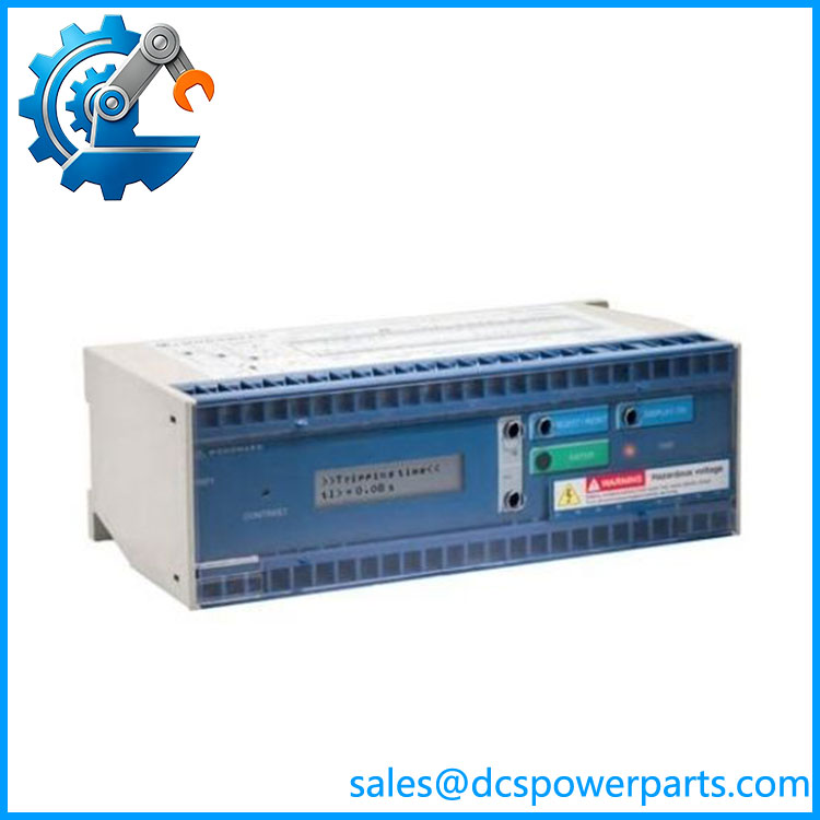
Woodward WIP1-3-I1-E1
Main Features and Engineering Considerations
. Communication Capability
The most important difference between this unit and a basic -1 is the RS-485 interface. Woodward’s order form idents as the version incorporating RS-485. The communication arrangement can use Woodward’s PRO OPEN DATA protocol or Modbus RTU when the corresponding option is selected. Therefoa -I1-E1 installed in a SCADA-connected switchgear panel should be checked against the existing communications configuration before replacement.
2. 1 A Current Transformer Interface
The I1 designation specifies the 1 A rated-current configuration. This is not a minor ordering detail. CT ratio, secondary current, burden, polarity, wiring resistance, and shorting arrangements all affect the suitability of the relay. A 5 A protection relay should not be substituted simply because it belongs to the same family.
3. Earth-Current Measurement
The E1 designation identifies the additional earth-current measurement function. The documentation shows separate IE> and IE>> protection elements for earth-current supervisiohis the suitable for protection schemes requiring both phase-current and earth-fault monitoring.
4. Self-Powered Architecture
The is fundamentally a CT-powered protection relay. The additional power pack available on -d provides the relay’s own supply; Woodward specifically notes that this power pack does not provide the tripping energy for the impulse output. This distinction should be considered when checking the breaker trip circuit.
5. Multiple Protection Curves
The supports multi-characteristic overcurrent protection, including definite-time and inverse-time behavior. The protection engineer should select pickup and delay settings based on the site’s coordination study. Factory/default values from the manual should never be treated as the correct settings for an installed feeder or generator.
6. Direct Trip and Relay-Contact Options
The supports both electro-pulse and relay-contact tripping. The selected arrangement affects the external breaker-trip wiring. Woodward documentation specifically states that an electro-pulse setting is required when a tripping coil is used.
Application Scenarios
- Generator overcurrent protection
- Generator earth-fault protection
- Industrial switchgear
- Feeder protection
- Electrical distribution panels
- Power-generation auxiliary systems
- Circuit-breaker protection
- SCADA-connected protection panels
- Legacy Woodward protection systems
- Industrial power systems requiring RS-485 monitoring
- Protection systems requiring CT-powered operation with additional earth-current measurement
Engineer’s Guide: Field Pitfalls
1. Do not coe with -1.
includes the RS-485 interface and additional-power-supply architectuWIP1-1 is a different hardware version.
2. Confirm the 1 A CT circuit.
The I1 designation means 1 A rated current. Verify the CT secondary before installation.
3. Confirm the E1 earth-current circuit.
The E1 configuration includes additional earth-current measurement. Check the earth CT wiring and polarity against the original panel drawings.
4. Verify the communications protocol.
Having an RS-485 interface does not by itself prove that the relay is configured for Modbus RTU. The order form distinguishes PRO OPEN DATA and Modbus RTU configurations.
5. Check the auxiliary supply option separately.
supports an additional power supply, but the 230 VAC supply is separately identified in the order form. Do not assevP1-3 has the same auxiliary-power arrangement.
6. Check the breaker trip method.
The relay supports electro-pulse and relay-contact tripping. The existing trip-coil voltage, trip energy, pulse arrangement, and terminal wiring must be verified before commissioning.
7. Preserve protection settings.
Record I>, I>>, IE>, IE>>, time delays, curve selection, blocking inputs, fast-trip settings, and communication parameters before removing an operating relay.
8. Check the software revision on legacy equipment.
The referenced documentation idents software as V13-1.06 for the documented unit description. Older and later revisions may differ, so the nameplate and actual installed firmware should be checked when matching a replacement.
Frequently Asked Questions
t dward ?
Ita self-powered time overcurrent relay configured for 1 A rated current, additional earth-current measurement, and an RS-485 communication interface.
What does “3” men ?
In Woodward’s order form, position 3 identifies the self-powered version with an additional power supply and RS-485 interface.
What does I1 mean?
I1 identifies the 1 A rated-current configuration. This is the CT interface rating and should be matched against the installed CT secondary.
What does E1 mean?
E1 identifies the configuration with additional earth-current measurement, providing the IE> and IE>> earth-fault protection functions.
Does support Modbus?
e hardware provides RS-485. Woodward’s order form allows either its standard PRO OPEN DATA protocol or Modbus RTU when the corresponding communication option is selected. The exact communication option should therefore be confirmed from the complete nameplate/order record.
Is self-powered?
. belongs to the self-powered1 architecture. It can also have an additional power supply, but Woodward notes that this power pack supplies the relay itself and does not provide the tripping energy for the impulse output.
Is a generator controller?
No. It is an electrical protection relay. It monitors current and executes configured overcurrent and earth-fault protection functions; it is not a generator speed governor, excitation controller, or PLC.
Procurement Note
Specify the item as:
dw WIP1-3 — 1 A rated current — additional earth-current measurement — RS-485 communication interface.
For an installed replacement, verify:
- Complete ordering code
- 1 A CT secondary
- Earth-current CT arrangement
- RS-485 wiring
- PRO OPEN DATA versus Modbus RTU configuration
- Auxiliary-power option
- Electro-pulse versus relay-contact trip method
- Breaker trip-coil characteristics
- Protection settings and inverse-time curve
- Firmware/software revision
- Existing flag-indicator and accessory configuration
The critical distinction is that is notply a WIP1-1-I1-E1 with a different labele hardware adds the RS-485 interface and supports an additional power-supply arrangement, making the complete ordering configuration important for both protection and SCADA integration.