Description
Product Overview
In distributed control and computing systems, exchanging data between processors can introduce communication overhead and timing uncertainty. The VMIC VMIVME-5576-210 addresses this requirement through a fiber-optic reflective memory architecture that automatically distributes written data across connected VMEbus nodes. Rather than requiring each receiving processor to poll a remote device or manage every transfer, the board mirrors data into corresponding local memory locations across the network. This arrangement supports coordinated operation among multiple computers used in industrial control, test systems, simulation, and other distributed computing applications.
The documented VMIVME-5576-210 configuration provides 1 MB of onboard memory, a 4K-transfer FIFO, and an ST/PC optical interface for 62.5 μm multimode fiber. The VMIVME-5576 family supports up to 256 network nodes and distances of up to 2,000 meters between nodes. Published transfer rates reach 6.2 MB/s without redundant transmission and 3.2 MB/s in redundant mode. Interrupt capability allows one node to notify another after data has been transferred, supporting coordinated processing when event timing matters. The VMEbus interface also supports A24 and A32 addressing, with D8, D16, and D32 data-access modes.
For maintenance engineers, the VMIC VMIVME-5576-210 is relevant when an existing system depends on reflective memory for data exchange between VMEbus computers. Replacement planning must account for memory capacity, FIFO configuration, optical connector type, node identification, jumper settings, and the host computer’s VMEbus configuration. A board with a different optical connector or memory option may require changes to the existing installation. The manufacturer lists the VME-5576 family as having entered a restricted production phase in December 2009, making revision identification and condition verification important when sourcing legacy hardware. Before returning a replacement to service, verify fiber continuity, node communication, memory synchronization, and interrupt behavior under the intended operating conditions.
Product Introduction (Non-Templated)
When several VMEbus computers must exchange data without constant processor intervention, reflective memory provides a direct method of distributing shared data. The VMIC VMIVME-5576-210 combines 1 MB of memory with fiber-optic communication, interrupt support, and a 4K-transfer FIFO. The family supports up to 256 nodes and link distances of 2,000 meters.
For a legacy system upgrade or replacement, match the memory and FIFO options, optical connector, node configuration, and VMEbus addressing requirements. Functional testing should include both ordinary data transfers and interrupt handling before production use.
Key Technical Specifications
| Parameter | Value |
|---|---|
| Product Model | VMIVME-5576-210 |
| Manufacturer | VMIC / GE Fanuc; legacy product family associated with Abaco Systems |
| Product Type | Fiber-optic reflective memory interface board |
| Series | |
| Form Factor | Single-slot, 6U VMEbus board |
| Memory Capacity | 1 MB |
| FIFO Configuration | 4K-transfer FIFO |
| Optical Connector | ST/PC |
| Fiber Type | Multimode, 62.5 μm core |
| Maximum Network Nodes | 256 |
| Maximum Distance Between Nodes | 2,000 m |
| Transfer Rate, Standard Mode | Up to 6.2 MB/s |
| Transfer Rate, Redundant Mode | Up to 3.2 MB/s |
| Serial Optical Signaling Rate | 170 Mbaud |
| VMEbus Addressing | A24 and A32 |
| VMEbus Data Access | D8, D16, D32 |
| Interrupt Capability | User-configurable interrupt levels |
| Operating Temperature | 0°C to 55°C |
| Storage Temperature | −40°C to 85°C |
| Power Requirement | +5 V DC, 5.0 A maximum |
| Network Topology | Fiber-optic daisy-chain ring |
| Condition | Not specified; verify actual unit and test records |
Specifications are based on the documentation and the published -210 configuration. Confirm the exact board markings and revision before using these values as acceptance criteria.
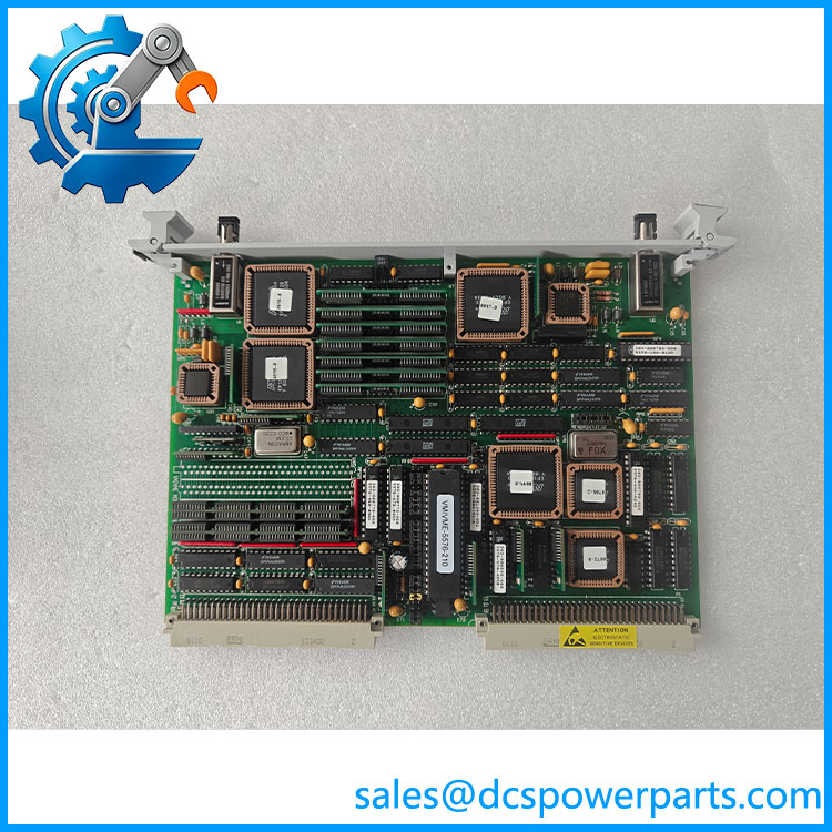
VMIVME-5576-210
Related Products
The following models and accessories are relevant to the -210 installation or replacement process. Memory options and connector arrangements must be checked carefully; related part numbers do not automatically indicate interchangeability.
1. VMIC -200 — A potential configuration comparison within the same board family. Confirm its memory, FIFO, and optical connector options against the original unit before considering substitution.
2. VMIC -110 — A related ordering configuration to investigate when comparing lower memory capacity or different FIFO options. Verify the complete configuration code and hardware documentation before ordering.
3. VMIC — The base family designation for the reflective memory board. It identifies the general platform, but not necessarily the exact memory, FIFO, and connector configuration required by an existing installation.
4. Abaco Systems VME-5576 — The family-level product designation associated with the legacy reflective memory interface. Use its documentation to review system capabilities and migration considerations; confirm the exact hardware configuration separately.
5. VMIC VMIVME-5577 — A related reflective memory product designation worth evaluating when reviewing legacy system architecture. Confirm its interface specifications, optical characteristics, and host compatibility before considering it as an alternative.
6. VMICBL-000-F3 fiber-optic cable assembly — A documented cable family for VMIC reflective memory equipment. Select the connector variant and cable length to match the installed ST optical ports and physical routing.
7. VMIC shared driver software — The associated software support package may be relevant when restoring communication on a host computer. Verify the operating system, driver release, and VMEbus interface requirements before installation.
8. VMIC optical interface components — The board documentation identifies optical transmitter and receiver components used by the interface. These may be relevant during hardware troubleshooting, but replacement component specifications and service procedures must be confirmed from the applicable technical documentation.
Frequently Asked Questions (FAQ)
the used for in an industrial control system?
The allows multiple VMEbus computers to share data through a fiber-optic reflective memory network. Data written to one board’s memory is distributed to corresponding memory locations on the other connected boards.
Typical uses include:
- Coordinating multiple real-time computers.
- Exchanging control and status data between distributed systems.
- Synchronizing processes through interrupt notifications.
- Sharing data in industrial test and simulation equipment.
It is a computer interconnect board, not a conventional PLC digital input or output module.
2. What is the diffeen and other configurations?
The suffix identifies a particular hardware configuration. For the -210 variant, published listings specify 1 MB of memory, a 4K-transfer FIFO, and an ST/PC optical interface.
When comparing another variant, check:
- Memory capacity.
- FIFO depth.
- Optical connector and fiber requirements.
- Board revision and ordering code.
- Compatibility with the existing driver and host system.
A matching base model number is not sufficient evidence that the board is a direct replacement.
3. Can I connect up to 256 nodes, and how far apart can they be?
The documented family supports up to 256 nodes, with a maximum stated distance of 2,000 meters between nodes. These are family-level limits, not a guarantee that every installation will achieve the maximum distance or node count.
Actual operation depends on the optical link budget, cable attenuation, connector condition, network topology, and configuration. Check the fiber specifications and node layout before expanding an installed network.
oes support redundant data transmission?
Yes. The family supports a redundant transmission mode intended to reduce the effect of transmission errors.
- Standard mode: Up to 6.2 MB/s.
- Redundant mode: Up to 3.2 MB/s.
Redundant transmission reduces throughput because data is transmitted redundantly. It should not be confused with a fully redundant hardware architecture or an independent safety certification.
5. Can the ?
Do not assume that hot-swapping is supported. The board uses a VMEbus interface, and safe replacement depends on the host chassis, system controller, operating software, and the consequences of losing that node.
Before removing the board, establish whether the system can tolerate a node outage. Follow the approved shutdown or maintenance procedure, preserve node configuration, and verify network recovery after installation.
6. Willthe erase my application logic or data?
Replacing the physical board does not necessarily erase application logic stored on the host computer. However, the replacement may require configuration of node identification, interrupt registers, and driver settings.
The board’s local reflective memory should not be treated as permanent storage for application logic. Back up host software and configuration files, document jumper settings, and verify data synchronization after replacement. If interrupts are used, check interrupt vectors and levels as part of commissioning.
7. How should I verify a new-surplus hed before purchase?
For a legacy board, request evidence tied to the actual unit rather than a generic specification sheet.
- Identification: Obtain photographs showing the full part number, serial number, and revision markings.
- Condition: Confirm whether the unit is unused, used, refurbished, or repaired.
- Functional test: Request evidence of VMEbus recognition, memory read/write operation, optical transmission and reception, and interrupt handling.
- Configuration: Verify the 1 MB memory option, 4K FIFO, and ST/PC connector arrangement.
- Warranty: Obtain written coverage terms and the procedure for handling a failed incoming inspection.
A visual inspection alone cannot establish that reflective memory communication works correctly across the network.
Procurement recommendaMIC is a 1 MB fiber-optic reflective memory board for 6U VMEbus systems, with a 4K-transfer FIFO and ST/PC optical interface. Its legacy production status makes exact configuration matching and functional-test evidence important. Before purchase, confirm the full board label, jumper settings, optical interface, and compatibility with the existing VMEbus host.