Description
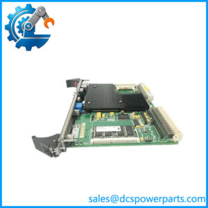
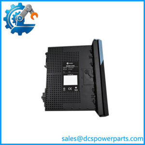
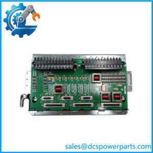
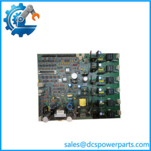
VMIC VMIVME-4150 Isolated Analog Output Board
Key Technical Specifications
| Parameter | Specification |
|---|---|
| Model | VMIVME-4150 |
| Product Type | Isolated Analog Output Board |
| Bus | VMEbus |
| Form Factor | 6U |
| DAC Resolution | 12-bit |
| Channel Configurations | 4, 8, or 12 |
| Voltage Outputs | ±2.5 V, ±5 V, ±10 V; 0 to +2.5 V, 0 to +5 V, 0 to +10 V |
| Current Outputs | 4–20 mA, 0–20 mA, or 5–25 mA |
| Voltage Load Capacity | 10 mA over the full ±10 V range |
| Voltage Output Accuracy | 0.05% |
| Current Output Accuracy | 0.08% |
| Isolation | Up to 1,000 V standard; higher isolation options are documented |
| Output Disconnect | Program-controlled for voltage-output configurations |
| Data Readback | Static readback registers |
| Field Connection | Front-panel access |
The uses optical data coupling and isolated DC/DC conversion to separate each analog channel from the VMEbus and from the other output channels. The board supports both voltage and current-output configurations, with the exact configuration determined by the installed output modules and hardware settings.
Product Introduction
The is a 6U VMEbus analog output board designed for applications requiring multiple isolated analog control signals. It provides up to 12 independent 12-bit DAC channels, with selectable voltage ranges and optional standard industrial current-loop configurations. Each channel is isolated from the VMEbus and from the other channels, making the architecture useful where ground potential differences or electrical interference could otherwise affect analog control signals.
In a legacy VME-based automation or test system, the typically sits between the VME CPU/control software and field-side devices such as proportional actuators, analog controllers, instrumentation, or other equipment requiring a voltage or current reference. Its static readback registers and programmable output disconnect function are useful during commissioning and maintenance because the host application can verify commanded output data and place voltage outputs in a controlled state during testing.
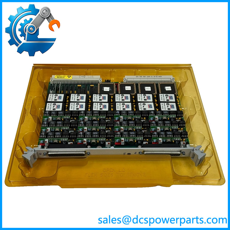
VMIVME-4150
Application Scenarios & Field Pitfalls — The Engineer’s Perspective
Engineering Pain Point
When a VME analog output board fails, the difficult part is often not finding another board with the same VME form factor. The real issue is matching the output configuration. A configured for bipolar voltage is not automatically equivalent to a current-output configuration, even though the base board designation is the same.
Typical Applications
- Legacy VME Control Systems: Provides analog command signals from a VME-based controller to external process equipment.
- Supervisory Control: Generates isolated voltage or current-loop references for industrial control equipment.
- Automatic Test Equipment: Suitable for isolated analog signal generation where multiple independent outputs are required.
- High-Interference Environments: Channel isolation helps prevent field-side ground differences from propagating through the VME backplane.
- Instrumentation Systems: Current-loop configurations can interface with conventional 4–20 mA process equipment.
Technical Pitfalls
- Do not mistake it for an analog input board. Some current online listings incorrectly describe the as a 16-channel analog input module. The manufacturer documentation identifies it as an isolated analog output board.
- Verify the output configuration. Voltage and current outputs use different hardware configurations. Check the original board’s ordering code, installed output modules, jumpers, and field wiring before replacement.
- Check the channel count. The family supports 4-, 8-, and 12-channel configurations. A generic “” description does not establish the exact population of the board.
- VME address configuration matters. The board uses VMEbus address spaces and host-side registers. A replacement may require the same address configuration as the original installation.
- Do not assume software compatibility from mechanical fit. The board can physically occupy a VME slot while still requiring the correct driver, register mapping, initialization sequence, and application configuration.
- Inspect the field connector before installation. Output wiring carries control signals directly to external equipment. Confirm pin assignments and output mode before applying a replacement board.
- Check output behavior during reset. The hardware provides program-controlled output disconnect functionality, and voltage outputs are also disconnected or placed in a defined state during reset depending on configuration. This behavior should be considered when the board is used for valve, actuator, or drive references.
Related Products
- VMIVME-4100 — VMIC analog output family member with a different channel architecture.
- VMIVME-4116 — 16-bit, 8-channel analog output board; different resolution and channel configuration.
- VMIVME-4132 — 12-bit, 32-channel analog output board; substantially different channel density.
- VMIVME-4145 — Four-channel 16-bit arbitrary waveform generator; intended for waveform generation rather than conventional multi-channel analog control.
- VMIVME-4514A — VME analog input/output scanning board; not a direct analog-output replacement.
- MVME-4150 — Later third-party VME analog-output replacement family; verify software and pinout compatibility rather than assuming drop-in equivalence.
- VMIVME-3456 — Related VMIC VME I/O hardware referenced with the for certain overvoltage-protection applications.
Procurement Note
For a replacement, the most useful purchasing information is the complete board part number, channel configuration, output type, jumper configuration, PCB revision, and photographs of the front-panel connector and board label. Do not approve a substitute based solely on the family name.
The product is a legacy platform item, and Abaco identifies the VME-4150 as having entered Restricted Production Phase in 2018. For an operating plant, a tested original board or a documented compatible replacement should be evaluated against the existing VME software and field wiring before installation.