Description
VIBRO-METER SIM-275A 200-582-500-013 | VM600 RPS6U Rack Power Supply | Replacement Power Module
Key Technical Specifications
| Parameter | Specification |
|---|---|
| Manufacturer | VIBRO-METER |
| Model | SIM-275A |
| Part Number | 200-582-500-013 |
| Product Type | Rack Power Supply |
| System | Machinery Monitoring / Protection |
| Rack Interface | 6U rack backplane |
| Input | 115/230 VAC or 220 VDC, according to published configuration data |
| AC Frequency | 47–63 Hz |
| Outputs | +5 VDC, +12 VDC, -12 VDC |
| Maximum Output Power | Up to 330 W reported |
| Typical Efficiency | 84% |
| Ripple and Noise | <50 mV peak-to-peak, 20 MHz bandwidth |
| Operating Temperature | 0°C to +70°C |
| Storage Temperature | -40°C to +85°C |
| Humidity | 5–90% RH, non-condensing |
| Installation | rack |
| Approx. Weight | 2.2 kg |
| Approx. Dimensions | 6 × 19 × 26.1 cm shipping/overall reference |
Published sources agree on the architecture, +5 VDC/±12 VDC outputs, 115/230 VAC or 220 VDC input configuration, 330 W maximum output, and 0–70°C operating range. Some secondary records give different current ratings and older power figures, so the exact nameplate should be checked before replacing a failed unit.
Product Introduction
The VIBRO-METER 200-582-500-013 is a rack power supply used to provide the regulated DC rails required by machinery protection and condition-monitoring electronics. Rather than processing vibration signals itself, the sits in the power architecture of the rack and supplies the +5 VDC and ±12 VDC rails used by installed monitoring and interface cards.
For maintenance teams, the important point is functional identity: VIBRO-METER 200-582-500-013 is a power module, so replacing it requires matching the rack, input configuration, connector arrangement, and power revision—not the sensor configuration of an MPC4 or other monitoring card. Published data also indicates that two units can be used for rack-level power redundancy, making this part particularly relevant when maintaining systems that cannot tolerate loss of the monitoring rack.
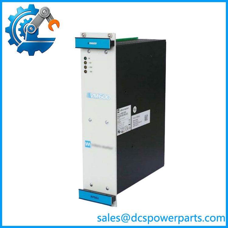
SIM-275A
Application Scenarios & Field Pitfalls — The Engineer’s Perspective
Engineering Pain Point
A failed rack power supply can make an entire machinery protection system appear dead even though the individual monitoring cards are healthy. This is why the should not be evaluated like a signal-processing module: the first checks should be incoming supply voltage, output rail condition, rack backplane connections, and PSU status rather than sensor calibration or channel configuration.
Typical Applications
- Steam and gas turbine monitoring: Supplies the rack supporting vibration, position, speed, and machinery protection electronics.
- Compressor protection: Maintains DC power for continuous machinery-condition monitoring systems.
- Industrial rotating equipment: Suitable for -based monitoring installations on pumps, motors, fans, and other critical machines.
- Legacy maintenance: Useful as a direct maintenance spare when the installed rack still depends on the power architecture.
Technical Pitfalls to Avoid
1. Do not confuse the part number with a signal module.
Several online records incorrectly describe 200-582-500-013 as a vibration monitor, I/O card, or high-speed pulse module. The more consistent identification is rack power supply.
2. Verify the input configuration before energizing.
Published records identify AC and DC-input variants, while some listings specifically associate this part number with 115/230 VAC input and others describe DC variants. Do not assume an AC/DC configuration from the designation alone. Check the actual nameplate and rack wiring against the installed unit.
3. Check output-current requirements, not only total wattage.
The +5 V rail carries a significant portion of the rack load. Published records show different current and maximum-power figures across revisions, including 330 W and older/lower power references. For a heavily populated rack, compare the installed PSU revision and rack load before substitution.
4. Inspect the backplane and redundant PSU arrangement.
If a replacement PSU immediately fails or its output rails are abnormal, do not assume the replacement unit is defective. Check rack backplane connections, cooling, downstream card loading, and the second PSU if redundancy is installed.
Related Products
- VIBRO-METER — The rack power-supply family to which belongs; verify exact input and revision before substitution.
- VIBRO-METER 200-582-500-013 — Exact procurement identifier for this / configuration.
- VIBRO-METER ABE04x Rack — rack architecture associated with power modules.
- VIBRO-METER MPC4 — Machinery protection card that can operate within the same rack; unlike , MPC4 performs machinery monitoring/protection functions.
- VIBRO-METER IOC4T — I/O terminal/interface hardware associated with monitoring configurations; it should not be substituted for the .
- VIBRO-METER CPUM — rack processing/communication hardware, functionally different from the rack PSU.
- VIBRO-METER IOC8T — Additional I/O interface option for compatible rack configurations.
- VIBRO-METER Redundant Configuration — Two compatible supplies can be installed where the rack architecture and load requirements call for redundant power.
Procurement Note
For 200-582-500-013, the complete part number matters more than the generic “” description. Before purchasing a replacement, compare the existing unit’s nameplate, input type, output ratings, hardware revision, rack configuration, and connector arrangement. For an operating protection rack, functional testing of all DC rails under the actual rack load is preferable to checking only whether the PSU powers up.