Description
UniOP eTOP306 Industrial HMI Operator Panel
Key Technical Specifications
| Parameter | Specification |
|---|---|
| Model | UniOP eTOP306 |
| Product family | eTOP Series 300 |
| Display technology | TFT color |
| Display size | 5.7 inches |
| Resolution | 320 × 240 pixels (QVGA) |
| Color depth | 64K colors |
| Backlight | LED |
| Typical brightness | 130 cd/m² |
| Touchscreen | Analog resistive |
| User memory | 64 MB internal flash |
| Ethernet | 10/100 Mbps |
| USB | Host interface, USB 1.1 |
| PC/printer port | RS-232, RS-485, or RS-422; software configurable |
| PLC port | RS-232, RS-485, or RS-422; software configurable |
| Auxiliary port | Supports optional controller or fieldbus modules |
| Power supply | 18–30 VDC |
| Maximum current consumption | 0.55 A at 24 VDC |
| Operating temperature | 0 to +50°C |
| Storage temperature | −20 to +70°C |
| Relative humidity | 5–85%, non-condensing |
| Front/rear protection | IP65 front / IP20 rear |
| Faceplate dimensions | 187 × 147 mm |
| Panel cutout | 176 × 136 mm |
| Mounting depth | Approximately 49 mm including allowance |
| Weight | Approximately 1.0 kg |
| Programming environment | UniOP Designer 6 |
| Listed approvals | CE, UL508, and Class I, Division 2 hazardous-location listing in the published technical note; verify markings on the actual unit |
Specifications are based on published eTOP306 technical documentation. Confirm the installed unit’s nameplate, hardware revision, and applicable approvals before using this table as a purchasing or engineering acceptance specification.
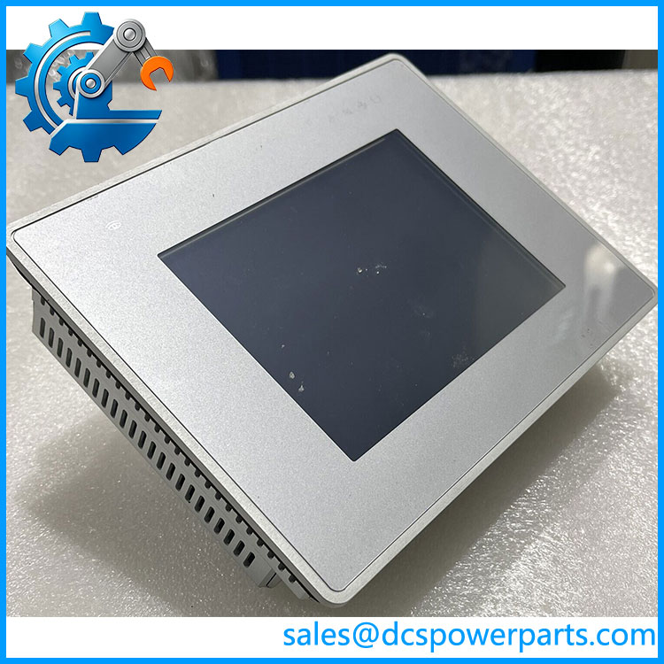
UniOP eTOP306
Product Introduction
The UniOP eTOP306 is a compact operator interface designed for machine-level visualization and control. Its 5.7-inch resistive touchscreen supports display of numerical values, text, bar graphs, alarm messages, trends, and recipe data. Ethernet and serial interfaces allow communication with supported controllers, while optional modules provide additional connectivity for certain fieldbus systems. The panel belongs to an older HMI generation, so software compatibility and application recovery are central considerations during maintenance.
The eTOP306 uses UniOP Designer 6 for application development. A replacement unit should not be approved based on screen size and connector appearance alone. Confirm the PLC driver, serial-port settings, Ethernet configuration, installed firmware, and availability of the original project file. If the original application cannot be recovered or transferred, a hardware replacement may require additional engineering work to recreate and validate the operator screens and control interactions.
Application Scenarios & Field Pitfalls — The Engineer’s Perspective
Engineering Pain Point
An HMI replacement can power up and display a screen while still failing to communicate with the PLC. The usual causes include a missing application project, an incompatible communication driver, different serial-port settings, an incorrect Ethernet configuration, or a change in controller addressing. Before removing the installed panel, document its configuration and establish whether the project can be uploaded, restored from backup, or transferred from the original engineering workstation.
Typical Applications
- Machine-status display and operator commands for PLC-controlled equipment.
- Alarm, event, and historical trend visualization.
- Recipe entry and operator parameter management.
- Maintenance of legacy machinery using UniOP eTOP Series 300 operator panels.
Technical Pitfalls to Avoid
- Secure the application before removal. Obtain the original Designer project and record its version, communication drivers, and any controller-specific settings. Do not assume a working HMI can always be uploaded into an editable project.
- Verify the PLC interface. Identify whether the installed controller communicates over Ethernet, RS-232, RS-485, or RS-422. Check cable pinout, baud rate, parity, station address, and protocol.
- Confirm the exact hardware variant. Published ordering information includes eTOP306U101, eTOP306U201, and eTOP306U301 variants with different front-panel colors. Verify the complete model code and connector arrangement.
- Check the power supply under load. Confirm the 18–30 VDC supply range and inspect voltage drop at the panel terminals during startup.
- Inspect the touchscreen and front seal. A damaged resistive overlay or aged gasket can affect operation and ingress protection. The stated front-panel rating assumes correct installation and sealing.
- Plan commissioning around the machine’s safe state. Verify operator commands, interlocks, alarm handling, and communication-loss behavior before returning the equipment to service.
- Check software support before purchase. Confirm access to the required Designer version, project files, drivers, and any optional communication module. A physically compatible panel is not automatically a functional substitute.
Related Products
These models belong to the broader UniOP eTOP family. They are useful for comparison, but they are not automatically drop-in replacements for the eTOP306.
- UniOP eTOP307 — 7-inch widescreen TFT panel with 800 × 480 resolution; different display dimensions and panel cutout.
- UniOP eTOP308 — 7.5-inch TFT model with 640 × 480 resolution; verify mounting and connection details.
- UniOP eTOP310 — 10.4-inch TFT operator panel with 640 × 480 resolution; requires a different mechanical installation.
- UniOP eTOP312 — 12-inch operator panel in the same broader series; confirm the exact hardware and display configuration.
- UniOP eTOP313 — 13.3-inch widescreen model; not a mechanical substitute for the eTOP306.
- UniOP eTOP315 — 15-inch panel intended for applications requiring a larger display; verify system and mounting compatibility.
The eTOP Series 300 operating documentation lists these models with differing screen sizes and resolutions. Project transfer, communication support, and physical compatibility must be assessed individually.
Procurement Note
When purchasing a UniOP eTOP306, request a photograph of the rear nameplate and connector panel, plus confirmation of the hardware and firmware revisions. Establish whether the original Designer 6 project and required PLC communication driver are available. Check the power input, panel cutout, serial pinout, Ethernet settings, and optional communication modules against the installed unit. For an older machine, include project recovery and functional commissioning in the replacement plan rather than treating the HMI as a simple display swap.