Description
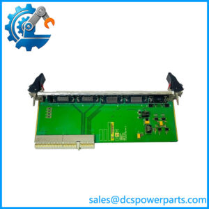
ULSTEIN PCC1030C Panel Controller Card
Product Introduction
In a HELICON-X propulsion installation, the operator panel is more than a collection of switches and indicator lamps. Commands have to be read, status information has to be updated, and those panel signals have to reach the main control unit without introducing ambiguity into the propulsion command chain. The ULSTEIN PCC1030C is the dedicated Panel Controller Card responsible for this layer of the system. The HELICON-X hardware manual states that it reads operator commands, transfers messages to the main unit and updates status lamps and indicators.
The ULSTEIN PCC1030C uses an Intel 80C196KB microcontroller running at 11.0592 MHz and communicates with the main unit through a serial CAN bus controller. It also contains analog and digital I/O resources, EPROM program storage and fixed RAM for operating data. This makes the card a system-specific controller rather than a generic PLC expansion board. For replacement work, the installed firmware, configuration jumpers, connector wiring and exact HELICON-X panel architecture should be checked before treating another PCC1030C revision as a direct substitute.
Key Technical Specifications
| Parameter | Specification |
|---|---|
| Product Model | PCC1030C |
| Product Type | Panel Controller Card / Panel Processor Card |
| System Platform | ULSTEIN HELICON-X |
| Primary Function | Operator-panel control and signal processing |
| Processor | Intel 80C196KB |
| Processor Clock | 11.0592 MHz |
| Program Memory | 64 KB EPROM socket |
| Installed RAM | 8 KB fixed RAM |
| Optional Serial EPROM | Socket prepared for up to 8 KB |
| Communication | Serial CAN bus |
| External Supply | 24 VDC ±10% |
| External Consumption | <50 W, dependent on J1/J2 interface-card load |
| Internal Supply | 5 VDC ±10% |
| Internal Consumption | <2.5 W |
| Analog Input Resolution | 10 bit |
| Analog Input Voltage Range | 0–5 V |
| Analog Input Current | 0.05 mA |
| Analog Input Impedance | 400 kΩ pull-up resistor |
| Maximum Relative Humidity | 97%, non-condensing |
| Ambient Temperature | 0–70°C |
| Vibration | 3–24 Hz at 0.05 mm/s; 22–100 Hz at 0.7 g |
| Height | ≤25 mm |
| Width | 100 mm |
| Length | 160 mm |
| Weight | <200 g |
The published HELICON-X documentation identifies PCC1030C specifically as the Panel Controller Card and separates its function from the IDA1035C main processor, DIO1037A digital I/O interface and AIO1036A analog I/O interface cards.
Application Scenarios & Pain Points
The failure symptoms can be misleading. A dead indicator, missing operator command or panel communication fault may look like a main-controller problem from the bridge. In a HELICON-X installation, the should be considered early because it sits directly in the operator-panel signal path.
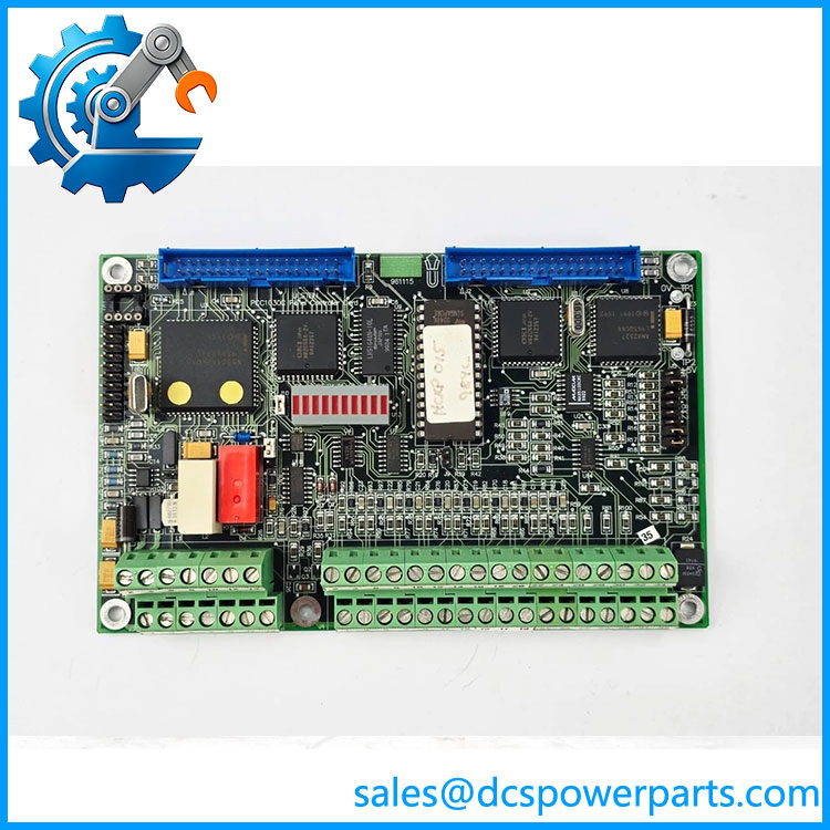
PCC1030C
- HELICON-X propulsion control panels: Reads operator commands and transfers the resulting messages to the main control unit.
- Propeller control consoles: Supports the panel-side electronics associated with propulsion command and status indication.
- Bridge operator interfaces: Handles digital and analog panel signals and updates connected status indicators.
- Legacy marine automation maintenance: Provides a replacement path where an existing HELICON-X installation remains in service and the original panel controller has failed.
The manual’s architecture is important here: is not simply an I/O card. Its microcontroller runs the panel-side operating functions, while the CAN interface carries information toward the main unit. Replacing a failed card therefore involves both hardware matching and firmware/configuration verification.
Related Products
- IDA1035C — Main Processor Card for the HELICON-X system. It handles the principal application processing and communicates with the various interface cards.
- DIO1037A — Digital I/O Interface Card for external digital field signals.
- AIO1036A — Analog In/Out Interface Card for analog field signals.
- PFI1038 — Pulse/Frequency Interface Card for pulse-related measurement and interface functions.
- PIB1039A — Pitch Indication and Backup Card associated with pitch indication functions.
- PDM1040 — Power Distribution and Monitor Card.
- PIC1041 — Pitch Interface Card.
- LKI1032 / LKI1932 — LCD and keyboard interface hardware associated with the panel architecture. A spare-parts record specifically documents the LKI interface as connecting with the .
These cards occupy different positions in the HELICON-X architecture. Physical similarity is not sufficient evidence of compatibility; the installed system drawing and card designation should determine the replacement.
Engineer’s Guide — Field Pitfalls to Avoid
1. Firmware is part of the replacement decision
The contains EPROM-based program memory. Spare-part records also associate assemblies with specific firmware identifiers, including HCX2435E1 and HCXP024.
Avoidance: Record the firmware marking from the existing card before purchasing. A board with the correct base model but incompatible application firmware can create a much harder commissioning problem than the original hardware failure.
2. Do not assume every is electrically identical
The base model is , but physical assemblies can carry different revision markings and associated part numbers.
Avoidance: Match the complete PCB label, revision, firmware EPROM and connector arrangement. The HELICON-X manual also states that a replacement card must be configured after installation.
3. Check the CAN bus before replacing the controller
Because the transfers panel information through the serial CAN bus, a bus fault can look like a controller failure.
Avoidance: Inspect CAN wiring, termination, connector integrity and neighboring nodes before declaring the defective.
4. Do not overlook the 32-terminal J4 connection
The documented has a 32-connection terminal block J4 intended for internal panel potentiometers and indicators.
Avoidance: Photograph and label the existing wiring before removing the card. A misplaced panel connection can produce several simultaneous symptoms and make troubleshooting unnecessarily difficult.
5. Verify the 24 VDC supply under load
The specified external supply is 24 VDC ±10%, while external consumption can reach below 50 W depending on the J1/J2 interface-card load.
Avoidance: Measure the supply at the card under operating load rather than checking only the unloaded cabinet power supply.
6. Treat configuration jumpers as functional settings
The includes configuration jumpers and interface circuitry. The HELICON-X documentation explicitly notes that replacement cards need configuration.
Avoidance: Compare jumper positions against the vessel’s original configuration documentation before powering the replacement.
7. Do not substitute a generic CAN controller
CAN communication alone does not make another controller compatible. The runs dedicated panel-control software and contains system-specific analog, digital and panel interface functions.
Avoidance: Replacement should be based on the complete HELICON-X card identity, firmware and configuration—not merely the presence of a CAN interface.
FAQ
What is the ULSTEIN used for?
The is the Panel Controller Card in the HELICON-X remote control system. Its documented functions include reading operator commands, transferring messages to the main unit and updating panel status lamps and indicators.
What processor does the use?
The documented hardware uses an Intel 80C196KB microcontroller with an 11.0592 MHz clock. The controller’s internal resources provide analog and digital I/O functions, while external EPROM provides program storage.
What power supply does require?
The HELICON-X hardware specification identifies an external supply of 24 VDC ±10%. Internal logic operates from a 5 VDC ±10% supply. External consumption is specified as less than 50 W depending on the connected J1/J2 interface-card load.
Does communicate over CAN bus?
Yes. The hardware manual identifies a serial CAN bus controller on the card. Digital and analog panel inputs are processed by the microcontroller and transferred to the main unit through this CAN-based system architecture.
Is interchangeable with DIO1037A?
No. They perform different jobs. is the panel controller; DIO1037A is the digital I/O interface card. Both can exist in the same HELICON-X system, but they are not functional substitutes for one another.
Does replacing require configuration?
Yes. The HELICON-X documentation explicitly states that a replacement card needs to be configured. The correct procedure should follow the vessel-specific HELICON-X documentation and the configuration of the removed card.
What should be checked before purchasing a replacement?
At minimum, record the model, PCB revision, firmware/EPROM identification, connector arrangement and existing configuration-jumper positions. Also confirm whether the failure is actually on the panel controller rather than the CAN network, power supply, panel wiring or another HELICON-X interface card. A spare-part record identifies as 10483, v1, but the installed card should be matched directly rather than relying on a catalog description alone.
What is the environmental operating range?
The documented specification gives an ambient operating range of 0 to 70°C and maximum relative humidity of 97% non-condensing. Mechanical dimensions are approximately 25 mm maximum height, 100 mm width and 160 mm length, with a specified weight below 200 g.