Description
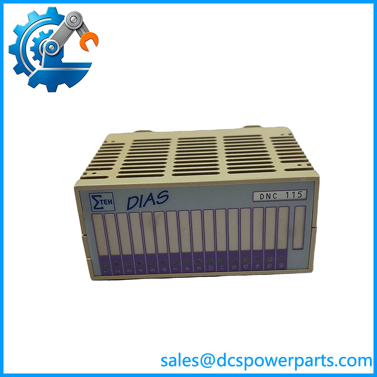
SIGMATEK DNC115 Positioning Module
Key Technical Specifications
| Parameter | Specification |
|---|---|
| Manufacturer | SIGMATEK |
| Model | DNC115 |
| Article Number | 05-011-115 |
| Product Type | 1-axis positioning module |
| Bus System | SIGMATEK DIAS |
| Encoder Channels | 1 |
| Encoder Signals | A, /A, B, /B, R, /R |
| Encoder Interface | RS422, 150 Ω load |
| Maximum Input Frequency | 125 kHz |
| Maximum Counter Frequency | 500 kHz |
| Counter Resolution | 16 bit |
| Quadrature Evaluation | 4× |
| Digital Inputs | 3 |
| Digital Input Voltage | 24 VDC typical, 30 VDC maximum |
| Digital Input Threshold | Low <8 V; High >14 V |
| Input Current | 5 mA at 24 V |
| Digital Outputs | 2 potential-free optocoupler outputs |
| Output Voltage | 30 VDC maximum |
| Output Current | 100 mA maximum |
| Analog Outputs | 1 |
| Analog Output Range | -10 to +10 VDC |
| Analog Resolution | 12 bit / 5 mV per bit |
| Analog Load | >100 kΩ |
| Analog Transient Time | <50 µs |
| Supply Voltage | 18–30 VDC |
| Current Consumption | <200 mA, including encoder supply |
| Operating Temperature | 0 to +60°C |
| Storage Temperature | -20 to +85°C |
| Protection | IP20 |
| Required Terminal | DKL 032 |
| Hardware Version | 1.x |
These specifications are taken from the SIGMATEK DNC 115 technical data sheet. The module provides three digital inputs, with input 3 capable of generating a hardware interrupt. Its two optocoupler outputs can be used for signals such as motor-control release and direction.
Product Introduction
The SIGMATEK DNC115 is a dedicated one-axis positioning module for the SIGMATEK DIAS automation system. It processes differential RS422 incremental-encoder signals, performs 4× quadrature counting, and provides a 12-bit analog command output from -10 to +10 VDC. Three 24 VDC inputs support reference and end-position monitoring, while two isolated optocoupler outputs provide auxiliary motion-control signals.
This architecture makes the DNC115 more than a basic digital I/O card. The module combines position feedback processing, reference/limit monitoring, analog motion-command generation, and discrete control outputs in a single DIAS bus module. The OEM documentation specifically illustrates applications involving DC servos and frequency converters.
DNC115
Application Scenarios & Field Pitfalls — The Engineer’s Perspective
Engineering Pain Point
When an older machine loses reliable position feedback, the failure is not always inside the encoder. Incorrect RS422 wiring, poor shielding, a damaged reference pulse, incorrect analog scaling, or a failed terminal module can all produce positioning errors that look like a motion-controller problem.
The DNC115 should therefore be tested as part of the complete encoder → DNC115 → analog drive command → motion-control path.
Typical Applications
- Single-axis machine positioning
- DC servo control
- Frequency-converter positioning applications
- Machine automation requiring incremental encoder feedback
- Legacy SIGMATEK DIAS motion-control systems
Technical Pitfalls
1. Verify the encoder wiring.
The expects differential A, /A, B, /B, R, /R signals at RS422 levels with a specified 150 Ω load. A single missing complementary signal can cause incorrect counting or an encoder-signal fault.
2. Understand the 500 kHz specification.
The data sheet distinguishes between 125 kHz maximum input frequency and 500 kHz maximum counter frequency, with 4× evaluation. These values should not be treated as interchangeable.
3. Check the analog scaling.
The analog output is -10 to +10 VDC with 12-bit resolution. The module’s internal conversion uses factory-stored offset and gain values in EEPROM. A replacement module should therefore be checked for correct calibration data before being judged against the original axis behavior.
4. Do not overlook Input 3.
Input 3 has a hardware interrupt function. If the machine program depends on that interrupt, simply confirming that the input LED changes state is not enough; the DIAS software configuration and edge detection need to be checked.
5. Use the correct terminal module.
The OEM specifies the DKL 032, Article No. 05-024-032, as the required terminal module. The uses a 17-pole, three-row spring-terminal connection through this interface.
6. Pay attention to analog wiring.
SIGMATEK specifically recommends keeping analog wiring short, separating it from digital signal wiring, using screened signal cables, and connecting the shielding to a common shield rail. These details matter when the axis is showing command-value noise or position instability.
7. Do not confuse with unrelated listings.
Some secondary catalogs incorrectly describe as an Ethernet controller, EtherCAT device, or 16-channel digital-output module. The SIGMATEK OEM document identifies the DNC 115 as a one-axis positioning module, Article No. 05-011-115.
Related Products
- SIGMATEK DKL 032 — Required terminal module for field wiring.
- SIGMATEK DIAS Bus System — Backplane/bus architecture used by the .
- SIGMATEK .fub — OEM software macro associated with the module.
- SIGMATEK DIAS positioning modules — Related motion-control hardware for legacy DIAS installations.
- SIGMATEK DIAS I/O modules — Complementary digital and analog modules used around the positioning system.
Procurement Note
For a replacement, specify SIGMATEK / Article No. 05-011-115 rather than relying on a generic description such as “digital output module.” Confirm the existing DKL 032 terminal module, encoder type, RS422 wiring, analog-drive interface, DIAS configuration, and machine software macro before installation.
The module is documented with hardware version 1.x, so firmware/software compatibility should be checked against the existing DIAS application when replacing a long-service unit.